As the lead engineering team at ShincoFab, we review hundreds of CAD files every week. Day in and day out, we see the exact same sheet metal design mistakes. They look perfect on your SolidWorks or AutoCAD screen, but they cause massive headaches when they actually hit our press brakes and laser cutters. For you, that means delayed shipments, scrapped parts, and a busted budget.
You want to design parts that are easy to manufacture and cheap to produce. In this guide, I will show you exactly how to do that based on thousands of real projects we’ve run through our shop floor. You will discover the most common design traps and the simple rules to fix them.
How Does Good Sheet Metal Design Save You Time and Money?
You design a part on your screen, and it looks perfect. But when it arrives from the shop, the holes don’t line up. We’ve all been there.
Just last month, a client sent us a complex bracket design with non-standard bend radii. We had to pause production for two weeks just to order custom tooling.
Getting your sheet metal design right the first time solves these headaches by making the manufacturer’s job easier and eliminating the need for manual workarounds. Good sheet metal design directly saves you time and money in three big ways:
- Lower quotes: Clean designs require less manual setup. If we can run your part on our automated CNC panel benders without swapping dies, you pay less money.
- Faster shipping: Nobody has to pause your project to email you about a broken CAD file.
- No wasted parts: You get exactly what you need on the first try.
How Do Design Mistakes Secretly Inflate Your Sheet Metal Quote?
Sheet metal design mistakes inflate your manufacturing quote by forcing fabricators to abandon fast, automated machinery in favor of expensive, manual labor and custom tooling. Here is exactly how your design choices secretly drive up costs on the production floor:
- Using Custom Bend Radii: CAD software lets you type in any bend radius you want. But on the shop floor, our operators use standard physical V-dies to air-bend the metal. If you pick a random radius (like 3.14mm instead of a standard tooling size), the shop has to order a custom tool or use a slow, manual process.

- Forcing Manual Setups: Automated machines are fast and cheap. Complex designs force shops to abandon these machines. If a worker has to manually load, turn, or tweak your part because a flange is too awkward to grip, labor costs skyrocket.
To get a cheaper quote from shops like ours, design with standard tooling in mind. Keep your bend radii consistent (e.g., matching the material thickness) across your entire part.
Phase 1: What Are the Most Common CAD and Material Mistakes?
Before you even think about bending metal, you must start with a flawless digital foundation. Let’s look at the foundational CAD and material errors that derail projects before they even reach the shop floor.
Can You Design Sheet Metal Like a Solid Block?
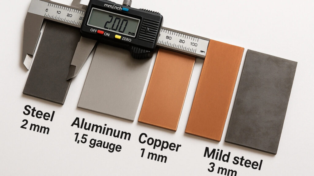
Sheet metal is a manufacturing material characterized by a uniform, flat structure that is cut and bent, rather than a solid block of steel that is carved into shape. This means your entire part must have the exact same thickness. We frequently reject files where a designer modeled a 16-gauge (1.5mm) box but somehow added a 3mm thick bottom panel in the assembly. Keep the material uniform everywhere.
What Are Realistic Tolerances for Sheet Metal Bending?
CNC Machining can hold crazy tight tolerances. Sheet metal cannot. Press brakes bend the metal. Bending stretches the material. Stretching shifts the final dimensions. If you ask for a tight ±0.002-inch (0.05mm) tolerance on a large folded aluminum enclosure, the shop will charge a fortune to try and hit it. A sheet metal tolerance is an acceptable dimensional deviation guided by standards like ISO 2768, usually hovering around ±0.010” to ±0.015”. Only use tight tolerances where parts actually connect.
Does Grain Direction Matter in Sheet Metal Design?
Material grain is a structural characteristic in rolled metals that dictates the direction of physical strength. When we use materials like 304 Stainless Steel or 5052 Aluminum, the grain dictates the strength. Press brakes apply force to the metal. Bending parallel to the grain weakens the structure. Weakened structures crack under pressure. Always design your part to bend across the grain.

Phase 2: What Are the Biggest Cutting and Bending Blunders?
Once your foundational CAD file and material choices are completely locked in, the next step is optimizing your design for the physical cutting and bending processes. This is where most theoretical designs fail in the real world.
Why Should You Avoid Sharp Internal Corners in Sheet Metal?
Perfect 90-degree internal corners look great on a screen. But in reality, lasers and punches cut the metal. Zero-radius cuts create stress risers. A stress riser is a localized microscopic defect. Defective areas concentrate physical force. Concentrated force tears the metal during bending. Small radii distribute this force. Distributed force prevents tearing.
How Close Can You Put a Hole to a Sheet Metal Bend?
Press brakes bend the metal. Bending stretches the material. Stretching distorts nearby holes. Distorted holes block fasteners during assembly. Use the industry-standard 4T rule (as widely recommended by The Fabricator): Keep all holes at least four times the material thickness away from the bend line.
Why Do You Need Bend Relief Cuts in Sheet Metal?
Think about folding a thick cardboard box. Bending machines fold the metal flanges. Folding forces the adjacent metal to move. Confined metal tears at the corners. Always design a small notch (at least the size of your material thickness plus the bend radius) where two bends meet. A bend relief is a specific CAD feature consisting of a small cut or notch that provides sheet metal the necessary room to stretch and move without tearing.
What is the Minimum Flange Length for Sheet Metal Bending?
A flange is a sheet metal feature characterized by a flat edge that is bent along a straight line. The press brake pushes the metal into the bottom die. The bottom die supports the flange. Short flanges lack sufficient surface area. Insufficient area causes the metal to slip. Slipping ruins the part. As a rule of thumb, make sure your flange length is at least 4 times the material thickness.
Phase 3: How Do Hardware and Finishes Affect Your Design?
After the metal is successfully cut and bent, your part still needs to be assembled and coated. Let’s transition to the post-fabrication stage and examine how hardware selection and finishing processes impact your final design.
Why Do You Need to Specify Exact Hardware Part Numbers?
Don’t just draw a hole and write “add nut here.” There are thousands of different fasteners. If you don’t list the exact part number (like a PEM® nut S-M4-1 or a specific standoff), our engineers have to guess. Tell us exactly what hardware you want so production keeps moving.

How Much Thickness Does Powder Coating Add to Sheet Metal?
Powder coating is a dry finishing process that adds a measurable physical layer of thickness to your part—usually between 0.002” to 0.005” per side, depending on The Powder Coating Institute (PCI) specifications. Powder coating adds physical thickness. Added thickness reduces hole clearances. Reduced clearances jam mating parts. Always make your holes and mating parts a little bigger to leave room for the finish.
Phase 4: How Should You Prepare Your Design for Handoff?
Now that your part is perfectly designed for manufacturing, assembly, and finishing, the final step is effectively communicating your vision to your fabrication partner. Here is how you should strategize your handoff.
How Does Sheet Metal Design Change from Prototype to Mass Production?
What works for a prototype will crush your budget in mass production. Take welding, for example. Manual TIG welding is fine for one quick aluminum box. But if you need 5,000 of them, paying a human to weld every seam takes forever. For high volume, we always advise clients to switch to spot welding, rivets, or interlocking tab-and-slot designs.
What Files Do You Need to Send to a Sheet Metal Fabricator?
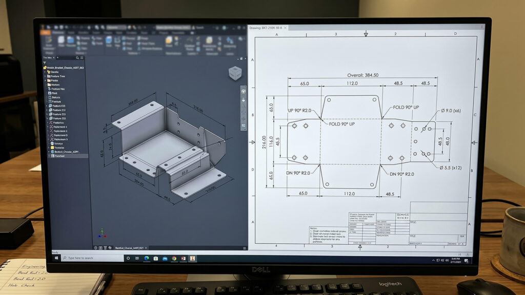
To get a fast and accurate quote, you must send your sheet metal fabricator a complete digital package that includes 3D CAD models, 2D flat patterns, and detailed engineering drawings. Use this exact checklist when submitting your files to ShincoFab or any other shop:
- STEP Files are universal 3D CAD models used to seamlessly transfer part geometry into fabricator CAM software (like Radan or Metalix).
- Flat Patterns are 2D geometric files (DXF/DWG) showing the exact flat, unbent state of a sheet metal part.
- PDF Drawings are technical reference documents calling out your exact material specifications, hardware, finish, and critical tolerances.
Conclusion
Designing sheet metal does not have to be a guessing game. When you follow these simple rules, you stop designing parts that are impossible or expensive to build.
Of course, even the best designs need a solid manufacturing partner to bring them to life. At ShincoFab, we cut, bend, and weld sheet metal every single day. We love seeing clean CAD files hit our inbox, but our engineering team also knows how to help you spot those sneaky mistakes before your metal ever hits the laser.
When you are ready for a quote, send your STEP files and PDFs over to us. Let’s get to work and turn your digital model into a perfect physical part.