As a Lead Production Engineer at ShincoFab, I review sheet metal CAD files every day. Want to know a secret? The number one reason parts fail on our factory floor isn’t bad machinery. It is a short flange.
QUICK ANSWER: The Minimum Flange Length Formula
Minimum flange length is determined by the physical relationship between material thickness, bend radius, and the factory’s V-die width. Minimum Flange Length is calculated by adding half of the V-die width, the material thickness, and the bend radius together.(Formula: Minimum Flange = [V-Die Width / 2] + Material Thickness + Bend Radius)
Over the last decade, I have watched press brakes turn hundreds of beautiful designs into expensive scrap because a designer guessed the flange length instead of doing the math. Last Tuesday, we had to halt production on a 500-piece aluminum enclosure order because the flanges were 2mm too short to span our bottom dies.

In this guide, I will show you how to replace rough estimations with exact engineering math. You will get the formula our operators use at ShincoFab to calculate minimum flange length for your specific material. We will break down how much money a bad bend costs, how aluminum differs from steel on our machines, and what to do if you need a super short flange.
By the end of this article, you will know how to design highly formable, consistent parts.
What Is a Flange (And Why Does Its Length Matter)?
If you look at a bent piece of sheet metal, you are looking at three distinct parts.
What Are the Basic Parts of a Sheet Metal Bend?
To understand what we see on our CAM software when we look at your CAD file, you must know the terminology. A sheet metal bend consists of three primary physical elements. Here are the basic components of a sheet metal bend:
- Base: The flat, stationary part of your design.
- Flange: The edge that gets bent upward or downward.
- Apex: The center of the bend. Think of it as the hinge.
Why Do Short Flanges Fail in a V-Die?
We bend sheet metal using a machine called a press brake. A top punch pushes the flat metal down into a V-shaped bottom tool called a die.
For this to work, your metal needs to rest securely across both shoulders of that “V.” If your flange is too short, it won’t reach across the opening. When the heavy punch comes down, the metal slips into the hole.

A short flange failing to span the V-die will often ruin a sheet metal part. When a flange slips into the V-die, it causes these three major manufacturing failures:
- Your bend angles will be incorrect.
- The metal edges will warp or crack.
- The slipping metal strikes and chips expensive steel tooling (we once lost a $2,000 precision V-die to this mistake).
If this happens, can an operator save the part? No. If a flange slips, it ruins the whole batch. A human operator cannot muscle a bad design into place against tons of machine pressure. If the length is wrong, you will pump out expensive scrap.
What Is the Difference Between a Supportable and Formable Flange?
There is a distinct difference between a marginal flange and one that works well. A merely supportable flange spans the V-die, while a truly formable flange sits flat, absorbs the pressure evenly, and bends consistently.
You might be tempted to design at the minimum limit to save space. Do not do this. You are taking a massive tolerance risk. At the bare minimum limit, the metal shifts slightly during bending. One part might bend at 90 degrees, while the next bends at 86 degrees. You lose bending consistency.
ShincoFab Floor Fact: Cheating the rules is expensive. When customers send us designs with a flange 1mm under the minimum required length, we historically see scrap rates spike to 35%. You are throwing away over a third of your material.
How Do You Measure Flange Length Correctly?
The correct measurement method depends heavily on how you design your parts.
How Do You Measure a Flange on a 2D Flat Pattern?
Are you working with a flat 2D drawing? The rule here is straightforward. Measure from the center of the bend line to the nearest cut edge. The bend line is where the press brake punch strikes the metal.
Always remember that metal stretches when you bend it. Your 2D flat pattern must account for this stretching. If you do not calculate the stretch properly, your final formed flange will be too short.
How Do You Measure a Flange on a 3D CAD Model?
Do you use 3D software like SolidWorks or Fusion 360? If so, your starting point changes. On a formed 3D model, you measure from the apex of the bend to the outer cut edge. The apex is the center of that outside corner.
To make sure your measurements are accurate, you must tell your software that you are making a sheet metal part. Always apply standard “sheet metal rules” in your program settings. This locks in your material thickness and allows the computer to handle the complicated stretch calculations for you.
How Does a Short Flange Impact Manufacturing Costs?
It is easy to think of a short flange as a minor design quirk. It is not. It is a severe financial drain. When you ignore minimum flange limits, you pay for it in three hidden ways.
First, you pay for the scrap. As I mentioned earlier, short flanges slip and warp. Every time a bend fails, that piece of metal goes straight into the recycle bin. But you still paid for that raw material. You also paid for the machine time it took to cut that ruined part in the first place.
Second, you risk destroying expensive equipment. When a short flange slips into the V-die, the press brake punch slams the metal against the steel shoulder of the die. This cracks or chips the tooling. Precision press brake tools cost thousands of dollars. Depending on the contract, if your bad design breaks a tool, the shop charges you for it. At the very least, it halts your production line while we source replacement tooling.
Third, you get hit with manual rework fees. If you demand a tiny flange, the shop has to cheat. They bend a much longer flange so it forms perfectly. Then, they take your part and physically machine the extra metal off on a CNC mill.
You turned a cheap, two-second bending operation into a slow, expensive machining job.
How Do You Calculate Minimum Flange Length?
Stop designing parts based on generic rules of thumb you found on Google. One of the most effective ways to control your manufacturing costs is to design for the specific V-dies your factory owns.
What Is the Standard Rule of Thumb for Flange Length?
You will see this rule everywhere in the sheet metal industry. People tell you to make your flange at least four to five times your material thickness. If you have a 2mm thick sheet, this rule says you need an 8mm to 10mm flange.
It is a decent starting point for a rough sketch, but it remains a guess. It ignores the physical tools hitting your metal.
What Is the Exact Formula for Minimum Flange Length?
Minimum flange length is determined by the specific relationship between your material thickness, your required bend radius, and the factory’s V-die width. Your flange must be long enough to span the tool, plus room to bend.
Minimum Flange Length is calculated by adding half of the V-die width, the material thickness, and the bend radius together.
The formula looks like this: Minimum Flange = (V-Die Width / 2) + Material Thickness + Bend Radius.
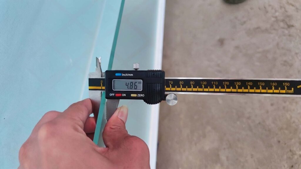
To use this, you need to know what V-dies exist on your factory floor. Don’t guess. Ask your shop what tools they use.
ShincoFab Tooling Cheat Sheet:
The standard V-die sizes used for mild steel depend primarily on material thickness. Here are the most common V-die widths used in sheet metal fabrication:
- 1mm thick metal: Uses a 6mm or 8mm V-die.
- 2mm thick metal: Uses a 12mm or 16mm V-die.
- 3mm thick metal: Uses a 20mm or 24mm V-die.
If your shop uses a 16mm V-die for your 2mm part, your flange must reach across half of that die (8mm). Add your 2mm thickness and your bend radius. Now you have a precise, formable target instead of a blind guess.
Why Does the Bend Angle Change Your Math?
This formula assumes you are making a standard 90-degree bend. But angles change the bending dynamics.
What if you are making a sharp, acute bend like 60 degrees? Acute angles force the punch to push the metal much deeper into the V-die. Because it plunges deeper, you need more flange length to keep the metal from slipping inside.
If your bend is tighter than 90 degrees, it is best practice to add extra length to your flange. Obtuse angles (like 120 degrees) do not go as deep, but it is always safest to stick to your baseline formula.
How Does Material Type Affect Minimum Flange Length?
Different metals bend differently.
Mild Steel (The easy standard)
Mild steel is the industry baseline. It is highly ductile, meaning it stretches and bends easily without breaking. If you calculate your flange length using the standard formulas we discussed, mild steel forms consistently. It is the easiest, most forgiving material to work with.
Aluminum (Why you need more room to prevent cracks)
Aluminum is tricky. It is much more brittle than steel. If you bend it too sharply, the outer edge snaps. To stop this from happening, operators must use a larger bend radius. A larger bend radius requires a longer minimum flange.
ShincoFab Case Study: 6061 vs. 5052 Aluminum
The specific aluminum alloy used directly impacts your minimum flange length limits. Here is how two common aerospace alloys compare on our press brakes:
- 5052 Aluminum: This is a soft, bendable alloy. You can use a tight 1.5mm bend radius. Because the radius is small, a short 6mm flange forms perfectly on our press brakes.
- 6061-T6 Aluminum: This stiff, aerospace-grade alloy offers incredible strength but is highly susceptible to cracking during forming. According to ASM International data, it requires a large inside bend radius (often 2.5 to 3 times the material thickness) to prevent micro-fracturing. Consequently, your flange must be designed longer than usual to span the wider V-die required for this generous radius, otherwise the metal will slip into the die and fail.
Stainless Steel (Handling high strength and springback)
Stainless steel is exceptionally strong. It takes about 50% more machine force to bend than mild steel. To handle that extreme pressure without breaking the tools, shops must use a wider V-die. Going back to our formula, a wider V-die automatically means you need a longer minimum flange.
Stainless Steel Springback: This material exhibits extreme elastic recovery and develops a persistent anticlastic curvature that forcefully resists unbending. To hit precise angles, press brake operators must program a heavy overbend. Consequently, your flange must be designed long enough to give the V-die sufficient leverage to execute this overbend—otherwise, the machine cannot grip it, leading to dimensional failure.

What Are the Most Common Flange Design Mistakes?
How Far Should Holes and Slots Be From the Bend Line?
Metal stretches right at the center of a bend. If you place a hole or a slot too close to that bend line, it stretches, too.
A perfect circle turns into an ugly oval. A straight slot gets warped. You cannot put a screw through a stretched hole. To fix this, you must keep your cutouts away from the danger zone.
The Fix: Push holes and slots away from the bend line. The distance from the edge of the hole to the bend should be at least three times your material thickness, plus your bend radius.
How Does the Backgauge Dead Zone Affect Flange Length?
How does a press brake operator know where to bend your part? They slide the flat metal into the machine until it hits metal stops called backgauge fingers. This backgauge ensures the bend happens in the same spot every single time.
But those metal fingers have physical limits. They cannot push infinitely close to the tooling. This creates a physical dead zone right behind the machine.
If your flange is too short, it will not reach the backgauge. If it cannot hit the stops, the machine cannot line up your part accurately. Your bend will be crooked. You should generally aim for a flange long enough to securely hit those backgauge fingers.
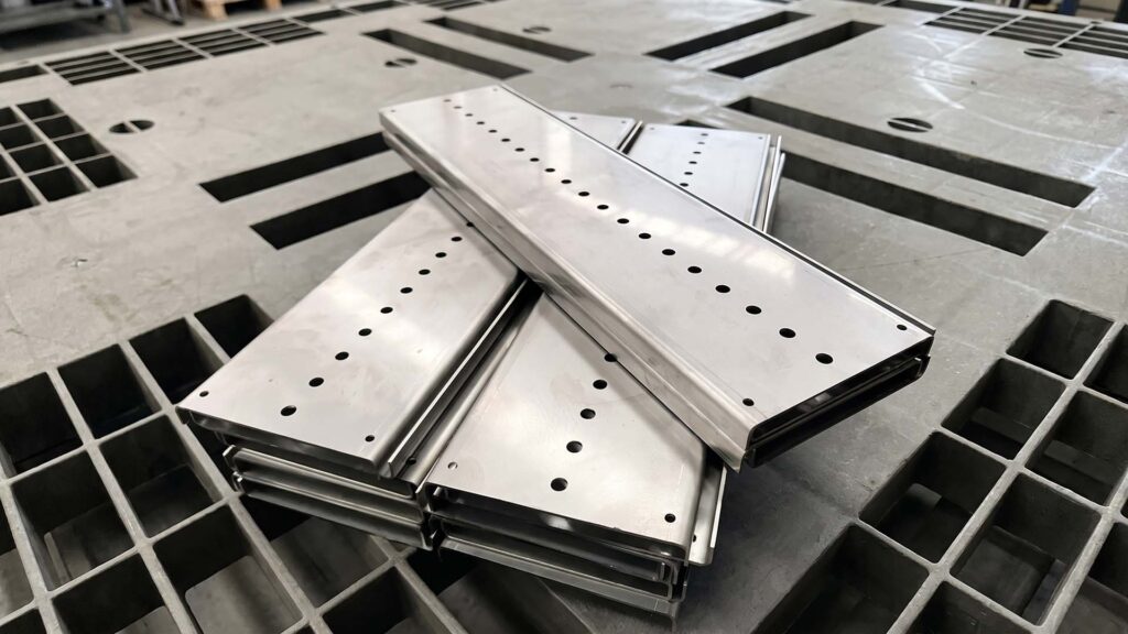
What Are the Options for Manufacturing a Super Short Flange?
Sometimes, you cannot compromise on design. Your part requires a tiny flange to fit into a tight assembly. When you hit this wall, you have two realistic options to get the job done at our facility.
How Does the Post-Bend Trimming Method Work?
The most common workaround is brute force. Our team uses the formulas we discussed to bend a standard, formable flange. Once the bend is perfect, we route the part to our CNC milling department and physically cut the extra metal off. This gives you the tiny flange you want with a perfect bend angle.
But you pay a heavy premium for this method.
The Cost Reality at ShincoFab: A standard press brake bend costs mere cents per part and takes seconds. When we add a secondary milling operation to trim that flange, the cost skyrockets by $10 to $20 per part. You are paying for a completely separate machine setup, extra operator time, and wasted material.
When Should You Use Rotary Bending or Hemming Tools?
The second option is to upgrade the physical tools hitting your metal. Instead of a standard V-die, shops use specialized rotary bending tools or hemming dies. Rotary tools fold the metal over a rotating cylinder instead of pushing it down into a hole. This bypasses the minimum length rules of a standard V-die.
These tools are specialized and expensive. When does it make financial sense to buy them?
It comes down to volume. If you are making 50 parts, do not buy custom tooling. Pay the estimated $15 per part for the machining rework, or go back to your CAD software and redesign the part. But if your production volume crosses 5,000 parts a year? The custom tooling pays for itself. The massive amount of time you save by skipping the CNC mill quickly covers the cost of the rotary dies.
When Does It Make Sense to Break Flange Length Rules?
The size of your order should dictate how strictly you follow the minimum flange limits.
Are you building a prototype? If you only need five parts, bend the rules. In prototyping, speed and proof-of-concept are the primary goals. Paying an average of $15 per part to machine down a short flange is fine. It adds roughly $75 to your total bill. You get your parts fast, you test your assembly, and you move on. The “cut it down later” method works perfectly here.
But mass production is a different universe. If you take that exact same prototype design and order a 5,000-part production run, you destroy your budget. That estimated $15 machining fee scales into $75,000 of avoidable overhead. Worse, trimming 5,000 flanges on a CNC mill takes weeks. You shatter your delivery lead times.
For mass production, you must design within the limits. You either change the part to meet standard V-die limits, or you invest in high-volume custom tooling up front.
What Should You Check Before Requesting a Manufacturing Quote?
Before you export that CAD file and ask for a quote, stop. Run your design through this final checklist. It takes two minutes, but it saves weeks of headaches and wasted money.
To ensure your sheet metal design is ready for manufacturing, review these four critical requirements before exporting your CAD file:
- Did you check the shop’s V-die list? Stop guessing. Ask your manufacturer for a list of the V-dies they own. Calculate your minimum flange length using their exact tools.
- Did you apply the 4x baseline? If you cannot get their tool list, did you at least apply the 4x material thickness rule? Make sure your flange has a fighting chance to span a standard die.
- Did you set your material bend radius? Update your CAD software rules before you measure anything. Remember, stiff aluminum requires a much wider radius than mild steel.
- Did you move your holes? Ensure your cutouts are safely out of the bend zone. Keep all holes and slots at least three times your material thickness away from the bend line.
If you check all four of these boxes, your design is officially ready for the press brake. You avoid expensive rework fees, drastically reduce scrap, and improve your chances of getting accurate parts on the first run.
Conclusion
Flange length is not a random number in your CAD software. It is a strict physical limit dictated by steel tools, machine pressure, and material properties.
By using the perfect fit formula and keeping your cutouts away from the bend line, you take control of your costs. You minimize wasted material, avoid expensive manual rework, and ensure your parts arrive as designed.
At ShincoFab, our engineering and fabrication teams review these details every day. We prefer helping you catch a short flange in the digital stage rather than calling you to report a failed bend on the factory floor.
Keep that pre-quote checklist handy and design for the tools on the press brake. When you do, your next manufacturing run will be faster, cheaper, and stress-free. If you’re unsure about your current CAD file, send it over to us and we will run the tooling math for you.