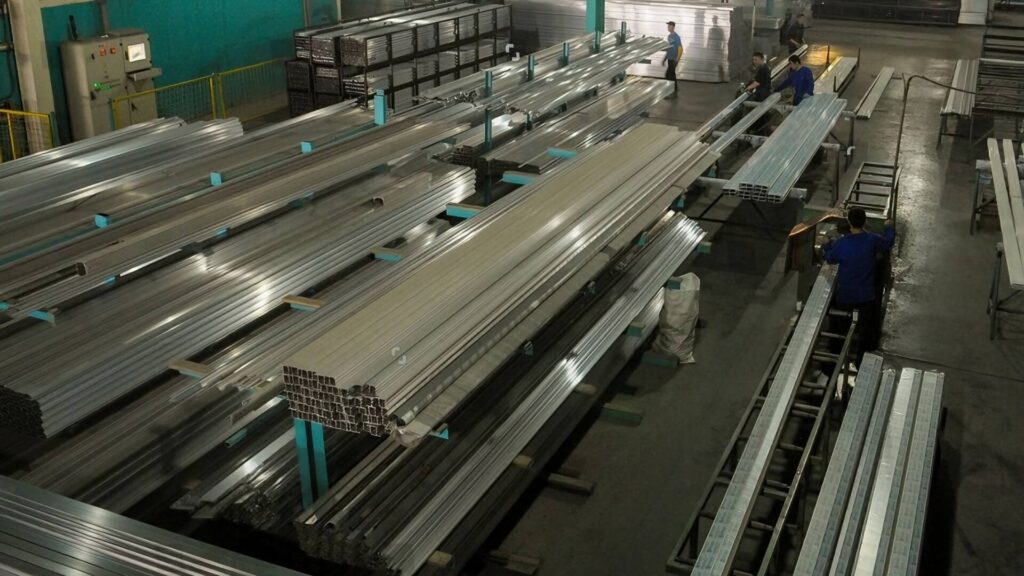
A comprehensive sheet metal DFM checklist ensures your CAD designs are optimized for factory-floor manufacturing, reducing scrap rates and avoiding costly custom tooling. I know this firsthand because I have reviewed thousands of CAD files before they hit the ShincoFab factory floor. Over my years as a manufacturing engineer here, I have seen recurring design mistakes ruin our clients’ budgets and delay critical product launches.
Stop guessing what the manufacturer wants. The design rules below come straight from our production lines at ShincoFab. Follow this guide to help cut your production costs, avoid weeks of delays, and get your parts made correctly on the first run.
Why Do You Need a Sheet Metal DFM Checklist?
How Does DFM Save Manufacturing Costs?
Design for Manufacturing (DFM) is a financial tool, not just an engineering chore. Every line on your CAD drawing is a price tag.
A 30-second mistake in CAD costs you dearly. Just last month at ShincoFab, a single misplaced hole on an enclosure triggered a custom tooling order that added $2,000 and three weeks of delay to a client’s project.
Implementing a proper DFM checklist before exporting your CAD files prevents many of these costly manufacturing errors. Catching design flaws early minimizes material waste, reduces the need for expensive custom tooling, and significantly accelerates your overall production timeline.
- Scrap Reduction: Standard tooling designs lower overall material scrap rates.
- Tooling Costs: Factory-aligned specifications avoid expensive custom tooling charges.
- Production Speed: Clean CAD files accelerate CNC machine setup and production times.
The Ultimate Sheet Metal DFM Quick Reference Cheat Sheet
Use the quick reference table below to check critical sheet metal DFM rules and understand the physical consequences of ignoring them on the factory floor.
| Feature | Rule of Thumb | Consequence of Failure |
|---|---|---|
| Minimum Hole Size | ≥ 1x material thickness | Snapped CNC punch tools ($500+ penalty) |
| Hole-to-Bend Distance | ≥ 2.5x material thickness | Stretched, oval holes; hardware won’t fit |
| Tab Width | ≥ 2x material thickness | Tabs break off during final assembly |
| Notch Width | ≥ 1x material thickness | Weak points snap during machine handling |
| Minimum Flange Length | ≥ 4x material thickness | Bottom die slips; crooked, inconsistent bends |
| Welding Clearance | ≥ 50mm radius line of sight | Weak, messy, or missed welds |
| General Tolerances | Use ISO 2768 standard | Up to 3x unit cost increase from manual QA checks |
| Powder Coating Clearance | Add 0.1mm to 0.2mm | Mating parts won’t fit; requires manual scraping |
How Do You Choose the Right Sheet Metal Material?
Which Sheet Metal Alloy Should You Use?

Match the metal alloy—and its temper—to the operating environment, required forming severity, and joining method. For coastal or marine-atmosphere applications with moderate chloride exposure, consider 316L stainless steel for marine environments. However, 316L is not fully resistant to direct seawater exposure or chloride crevice conditions, so severe saltwater service may require a higher-alloy stainless steel.
For parts requiring substantial bending or cold forming, choose 5052 aluminum in an appropriate temper. Fully annealed 5052 offers good formability, while harder tempers trade some bendability for higher strength.
Once you select an alloy, production volume, geometry, tolerance requirements, material utilization, and tooling cost determine the most economical manufacturing method. Laser cutting avoids dedicated blanking dies and supports rapid design changes, whereas stamping can lower the per-part cost when tooling is amortized across sufficient repeat volume.
- Stamping Molds: Custom stamping molds typically become cost-effective between 5,000 and 10,000 units.
- Laser Cutting: Laser cutting handles production volumes below 5,000 units efficiently.
- Cost Prevention: Standard CNC processes prevent large upfront tooling costs for lower volumes.
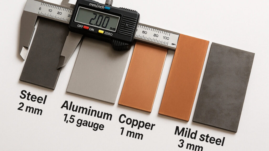
Why Should You Use Standard Sheet Metal Gauges?
Prioritize standard regional material thicknesses that we keep in stock. Specifying a 2.3mm thickness instead of the standard 2.5mm forces us to source custom-milled sheets just for your run. This simple specification error can easily add up to a 40% cost increase to your material bill. Check ShincoFab’s standard stock list before finalizing your design.
How Does Grain Direction Affect Sheet Metal Bending?
Metal grain direction significantly impacts the structural integrity of bent parts. Sheet metal forms a grain during the rolling process, and bending parallel to this grain causes hard metals to crack, snap, or weaken under the intense pressure of press brakes.
- Grain Fractures: Bending parallel to the grain often fractures hard metals like 6061-T6 aluminum.
- Perpendicular Alignment: Perpendicular bend lines help preserve the metal’s structural strength.
- Defect Prevention: Proper grain orientation minimizes micro-cracking during press brake operations.
How Do You Design Holes, Slots, and Cutouts?
What is the Minimum Hole Size for Sheet Metal?
There is no single minimum hole size for every sheet-metal process. For laser-cut parts, a practical design-for-manufacturability guideline is to specify a hole diameter at least equal to the material thickness. For example, specify a 3 mm or larger hole in 3 mm sheet when consistent edge quality and dimensional accuracy are important. Smaller holes may still be possible, but they can increase the risk of taper, dross, heat distortion, or inconsistent hole geometry.
For turret punching, the feasible minimum hole size depends on the sheet material, thickness, tool geometry, and press capability. AMADA’s Strong Punch Tool is designed to produce holes as small as 56% of the material thickness under suitable conditions. Do not assume that this represents a universal production rule; confirm the minimum manufacturable diameter with your fabricator before releasing the design.
Avoid specifying undersized holes without a process review. Extremely small laser-cut features can compromise cut quality, while very small punched holes may require specialized tooling or additional operations. These requirements can increase setup time, tooling wear, inspection needs, and overall part cost.
What are the Design Rules for Notches and Tabs?
Notches and tabs require specific width-to-thickness ratios to survive manufacturing handling and final assembly. Designing these features too thin creates weak points that easily break off under stress or during the press brake forming process.
- Tab Width: Tabs require a minimum width of twice the material thickness.
- Notch Width: Notches need a minimum width equal to the material thickness.
- Feature Strength: These minimum proportions prevent features from snapping during final assembly.
How Far Should a Hole Be from a Bend Line?
Placing holes too close to a bend line causes the metal to stretch and distort during the forming process. Maintaining a safe distance ensures holes remain round and undistorted, preventing hardware misalignment during final assembly and maintaining structural integrity.
- Minimum Distance: Hole centers require a minimum distance of 2.5 times the material thickness from any bend edge.
- Deformation Prevention: Adequate spacing minimizes hole distortion during the folding process.
- Hardware Fitment: Round holes facilitate smoother hardware insertion during final assembly.
What Are the Core Sheet Metal Bending Guidelines?
How Do You Calculate Minimum Bend Radius?
The minimum bend radius for sheet metal is the tightest internal curve a specific alloy can form without cracking. Exceeding this limit causes micro-fractures, weakens the structural integrity, and increases scrap rates during press brake operations.
- Visual Limitations: Visual inspections often miss structural micro-cracks from excessively tight bends.
- Field Failures: Hidden micro-cracks can cause parts to snap under mechanical vibration.
- Limit Verification: Manufacturer datasheets dictate the recommended minimum bend limits for each alloy.
Why Do You Need to Add Bend Reliefs?
A bend relief is a small cutout placed exactly where two bends meet at a corner. Without these specific reliefs, the metal material will stretch, tear, and likely deform as it tries to occupy the same space during the folding process.
- Relief Placement: Corner intersections require small circular cutouts called bend reliefs.
- Material Expansion: Bend reliefs absorb material stretching during the folding process.
- Tear Prevention: These cutouts minimize corner tearing and maintain structural integrity.
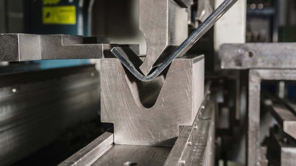
What is the Minimum Flange Length for Press Brakes?
The minimum flange length dictates whether a press brake’s bottom die can securely grip the sheet metal during bending. Designing flanges that are too short results in crooked, inconsistent folds and makes precision manufacturing highly unreliable for the machine.
- Minimum Length: Press brakes require a minimum flange length of 4 times the material thickness.
- Machine Grip: Adequate flange length provides physical leverage for the bottom die.
- Bend Consistency: Proper die grip supports straight, consistent, and precise bends.
How Do You Design for Sheet Metal Hardware Assembly?
Why Should You Avoid Custom Fasteners?
Specifying custom or imperial fasteners for a factory operating on the metric system can create severe supply chain bottlenecks. Using non-standard hardware drastically increases unit costs and extends manufacturing lead times unnecessarily, risking your product launch schedule.
- Lead Times: Custom fasteners can turn standard 2-day lead times into 4-week supply chain delays.
- Cost Increases: Non-standard hardware significantly increases overall unit costs.
- Standardization: Off-the-shelf hardware keeps manufacturing schedules on track.
How Much Clearance is Needed for PEM Tooling?
Self-clinching nuts require sufficient installation-tool access for both the punch and the anvil. During installation, the fastener must seat in the anvil, and the punch and anvil must apply force through parallel surfaces until the nut head contacts the sheet. PEM’s self-clinching-nut installation guidance specifies this installation method and recommends using the appropriate tooling for the selected fastener.
There is no universal clearance dimension for every PEM nut. The required clearance depends on the fastener family, thread size, sheet thickness, nearby bends or formed features, and the geometry of the selected punch and anvil. For exact part and tooling dimensions, consult the official PEM self-clinching nut data sheet, which identifies the recommended mounting-hole sizes and applicable anvil configurations.
Design the panel so that the installation tool can reach the hole without interference from flanges, bends, hems, adjacent hardware, or other highly cold-worked areas. If tool access is not verified early, the fastener may need to be installed before forming, with specialized tooling, or through a revised part design.
- Tooling Clearance: Hardware insertion machines require physical space around installation holes.
- Flange Proximity: Tall flanges block the anvil of the PEM insertion tool.
- Redesign Prevention: Early 3D model clearance checks prevent last-minute factory redesigns.
How Much Clearance Do Welders Need?
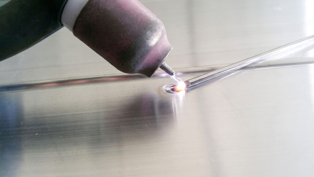
Welding tools require a clear, unobstructed line of sight to properly fuse metal joints. Whether using robotic welding arms or human operators, burying a weld inside a tight, inaccessible corner results in a weak, messy, or poorly executed weld.
- Torch Clearance: Standard welding torches require a minimum 50mm clearance radius.
- Line of Sight: Welders need direct visual access to fuse metal joints properly.
- Weld Strength: Adequate physical space is critical for strong, clean welding beads.
What Are the Best Tolerances and Finishes for Sheet Metal?
Which General Tolerances Should You Apply (ISO 2768)?
Do not apply unnecessarily tight tolerances to non-critical sheet-metal dimensions. Tighter requirements can increase manufacturing effort, inspection requirements, rejection risk, and overall part cost without improving the part’s functional performance.
For current ISO-based drawing practice, use ISO 22081:2021 general geometrical and size specifications to define and interpret general geometrical specifications and general size specifications on technical product documentation. ISO 22081:2021 is a published International Standard and replaces the withdrawn ISO 2768-2:1989.
Apply individually specified tolerances to dimensions and features that control fit, assembly, sealing, alignment, or functional interfaces. For all other applicable features, define a clear general-specification approach in the drawing or model and confirm the interpretation with the manufacturer before production. ISO 22081 provides rules for specifying and interpreting these general requirements; it does not provide a universal “fine/medium/coarse” tolerance table to substitute for engineering judgment.
- Cost Multiplication: Aerospace-level tolerances can triple unit costs due to manual QA measurements.
- General Standards: ISO 2768 provides sufficient precision for standard sheet metal brackets and enclosures.
- Targeted Application: Critical mating surfaces alone require tight, specific tolerances.
How Do You Specify Cosmetic vs. Hidden Surfaces?
Clearly specifying cosmetic versus hidden surfaces on your 2D drawings prevents factories from polishing unnecessary areas and overcharging you. Overseas manufacturers rely heavily on explicit drawing notes rather than informal email communications to determine your final finishing requirements.
- Drawing Notes: 2D PDF drawings require bold, color-coded finishing notes.
- Explicit Labeling: Explicitly labeling specific surfaces as cosmetic dictates factory polishing requirements.
- Overcharge Prevention: On-drawing instructions prevent factories from overcharging for unnecessary polishing.
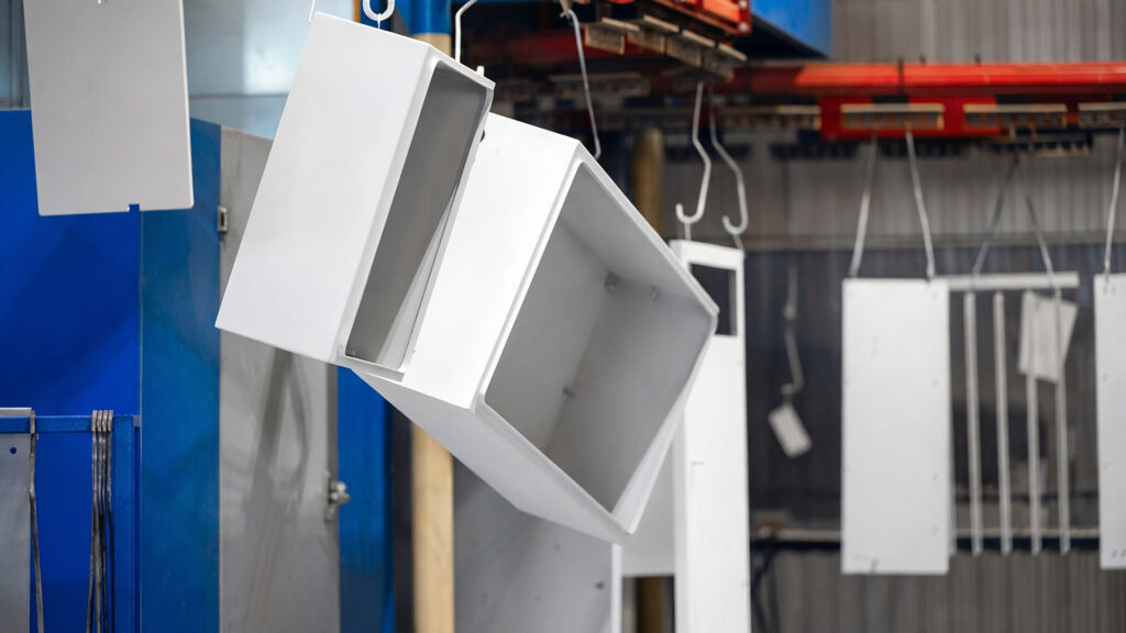
How Much Clearance is Needed for Powder Coating?
Powder coating adds measurable thickness to your final sheet metal parts, which can ruin the fitment of tightly mating components. Adding dedicated coating clearance to your initial CAD model ensures parts assemble smoothly without requiring manual paint scraping.
- Coating Thickness: Powder coating adds 0.1mm to 0.2mm of physical thickness to sheet metal parts.
- CAD Adjustments: CAD models require added clearance to accommodate this paint layer.
- Assembly Smoothness: Pre-planned clearances prevent manual paint scraping during final assembly.
How Do You Prepare CAD Files for Manufacturing?
How Does Nesting Parts Reduce Shipping Costs?
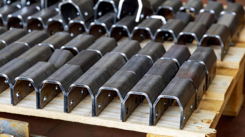
Nesting sheet metal parts allows them to stack seamlessly inside one another, minimizing wasted space during transit. Optimizing flange angles for stackability prevents you from paying exorbitant ocean freight costs to ship boxes full of empty air.
- Flange Adjustments: Tweaking flange angles by just 1 to 2 degrees can often enable part nesting.
- Space Optimization: Nested parts reduce empty air inside shipping containers, sometimes doubling the number of parts per box.
- Cost Reduction: Efficient stacking drastically cuts shipping volume, which can save thousands of dollars in ocean freight costs per container.
What is the Best Way to Export Sheet Metal CAD Files?
Exporting clean, properly formatted CAD files accelerates the quoting process and prevents downstream manufacturing errors. Messy 3D models force CAM engineers to guess your design intent, leading to endless email chains and severe production delays.
- File Formats: DXF and STEP files provide the cleanest flat patterns for manufacturing.
- Line Isolation: Isolated bend lines clarify design intent for CAM engineers.
- Quote Speed: Clean CAD files enable the ShincoFab quoting process to drop from 5 days to just 24 hours.
Conclusion
Design for Manufacturing is your best defense against blown budgets and missed deadlines. The rules on this checklist are designed to protect your bottom line, based on years of hard-won lessons on the ShincoFab floor.
Do not wait until the factory emails you with a list of problems. Take control of your design right now. Run your CAD files through these steps before you send out your next RFQ to pave the way for faster quotes, cheaper parts, and a smoother production run. Print this checklist, keep it next to your screen, and when you are ready, the ShincoFab team is here to bring your parts to life.