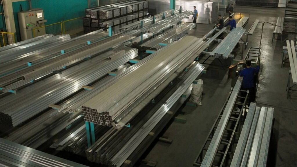
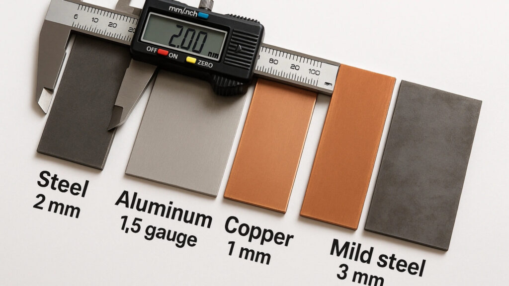
Deep draw sheet metal forming is a high-volume manufacturing process that turns flat sheet metal (blanks) into hollow, seamless 3D shapes. As an engineer with 15 years on the ShincoFab factory floor, I have watched this process create thousands of high-precision parts—and I know exactly how it fails when corners are cut on tooling.
While deep drawing is a highly efficient process for high-volume production, it is a major investment, not a quick fix. One wrong die clearance or a bad choice of metal temper can cost you thousands of dollars in ruined steel tools.
In this guide, I will show you exactly how deep draw sheet metal works based on our daily operations at ShincoFab. You will learn how to pick the right alloys, test your design before buying expensive tooling, and how our engineers fix common factory defects like wall thinning and flange wrinkling.
If you want to save money and get your parts made right the first time, you are in the right place.
The Basics of Deep Draw Manufacturing
How the Process Works on Our Floor
Deep drawing is a sheet metal forming process where high-tonnage presses use a hardened steel punch to force a flat metal blank into a die cavity. The intense pressure stretches the material, transforming the flat sheet into a seamless, hollow 3D shape without fracturing the metal.
The 4 Main Parts of the Setup
A deep draw press setup relies on four primary components to function properly.
- The Blank: The starting flat material, precisely laser-cut or stamped before forming.
- The Die Cavity: The hardened steel mold (often D2 tool steel or carbide for high-volume runs).
- The Punch: The solid ram that forces the blank down into the die cavity.
- The Blank Holder (Binder): It clamps the edges of the metal down, controlling the material flow to stop wrinkling as the punch stretches it.
Everyday Examples of Deep Drawn Parts
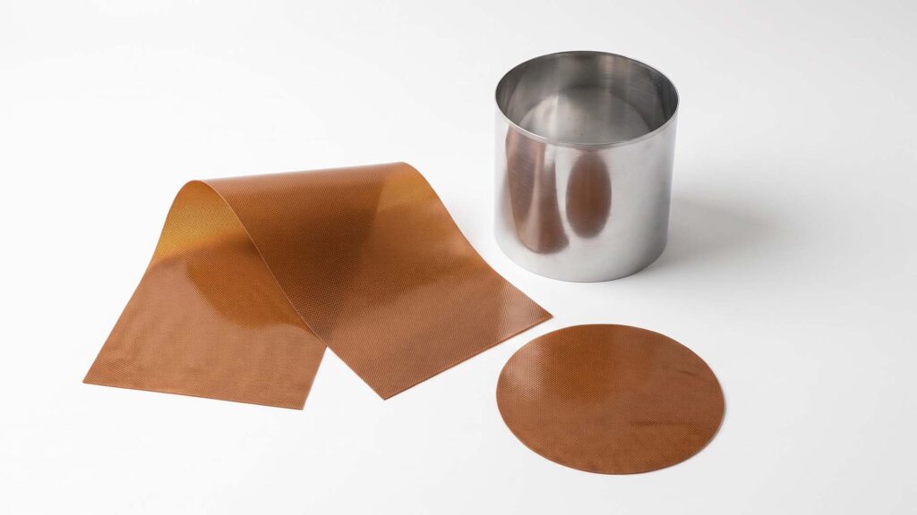
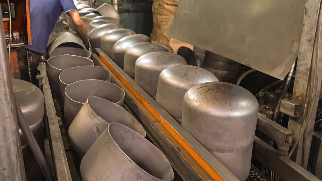
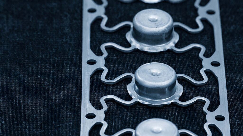
Deep drawing is commonly used to produce seamless, hollow metal components such as beverage cans, automotive oil pans, and cylindrical battery casings. It is particularly well suited to high-volume parts that need a continuous wall without welded seams.
To illustrate the production scale possible with transfer-press stamping, ShincoFab’s automated transfer presses can produce up to 3,600 seamless aluminum sensor housings per hour on our 600-ton hydraulic press. This type of high-volume forming application aligns with the capabilities of AIDA’s transfer and stamping press systems, which are designed for applications including transfer-die and high-speed metal forming.
Why Should You Use Deep Drawing? (The Benefits)
Stronger, Seamless Parts
Welded seams introduce potential weak points. Welds can crack under pressure and leak. Because a deep-drawn part is formed from one solid piece of metal, its grain structure is continuous. The cold working process actually strain-hardens the metal, making the final walls stronger than the original flat sheet.
Drastic Material Savings
Cutting metal on a CNC creates expensive scrap. Because deep drawing stretches metal rather than cutting it away, we consistently help clients reduce raw material waste by 40% to 60% compared to traditional CNC turning.
Perfect for High-Volume Runs
Once ShincoFab builds your custom progressive or transfer die, the process is incredibly fast. However, achieving this high production speed requires a significant upfront capital investment in custom tooling.
How Much Does Deep Draw Tooling Cost?
Understanding the Break-Even Point
Deep drawing is not for prototyping 50 parts. Procurement teams frequently ask exactly how many parts they must order to justify the upfront tooling investment.
Depending on part size and complexity, a custom hardened steel die set at ShincoFab typically costs anywhere from $5,000 for a simple single-stage draw tool to $30,000+ for a multi-station progressive die.
Because of this upfront investment, determining your break-even point depends heavily on the cost of alternative manufacturing methods. However, for most standard commercial parts, we generally see the tooling costs justify themselves when ordering 10,000 to 20,000 parts annually.
If you only need 500 parts, this process will drain your budget (we usually recommend metal spinning for that). But if you need 50,000 parts, the tooling cost amortizes to pennies per piece.
Deep Drawing vs. Metal Spinning vs. Metal Stamping
When choosing between deep drawing, metal spinning, and traditional metal stamping, engineers must balance production volume with critical design requirements like tolerances, wall thickness uniformity, and draft angles. The comparison table below breaks down the key differences to help you choose the right process.
| Manufacturing Process | Typical Ideal Volume | Typical Tolerances | Wall Thickness Control | Draft Angles Required? | Estimated Tooling Cost |
|---|---|---|---|---|---|
| Deep Drawing | High (Often 10,000+ parts) | Tight (±0.005″) | Highly uniform (slight thinning at radii) | Minimal to zero | High (Typically $5,000 – $30,000+) |
| Metal Spinning | Low to Medium (Varies, often 50 – 5,000) | Looser (±0.015″ to 0.030″) | Variable (often thins significantly) | None required | Low (Usually $500 – $2,500+) |
| Metal Stamping | Extremely High (Often 50,000+) | Tight (±0.002″ to ±0.005″) | Uniform (original sheet thickness) | None required | Highly Variable (Depends on die complexity) |
As shown above, if you need a tight tolerance and highly uniform wall thickness on a high-volume run, deep drawing is generally the optimal choice. However, if your design allows for looser tolerances and you only need a prototype run without investing in expensive hardened steel dies, metal spinning is your best alternative.
What Are the Best Metals for Deep Drawing?
Choosing Your Material & Tooling Lifespan
At ShincoFab, material selection directly affects deep-drawing performance, tooling maintenance requirements, and achievable part geometry. When drawing tougher grades such as stainless steel 304 or 316, elevated contact pressure and friction can increase the risk of adhesive wear and galling on the die surface. To maintain consistent part quality, these materials may require optimized lubrication, suitable die-steel selection or coatings, and more frequent inspection and polishing. Stainless-steel forming galling is therefore an important tooling consideration rather than an unavoidable outcome.
For applications prioritizing deep drawability, alloys such as 3003-O and 5052-O aluminum can be strong candidates when their corrosion resistance, strength, and forming requirements match the finished part. Low-carbon deep-drawing sheet such as DC04 is also specifically classified for deep-drawing applications. Final material selection should balance draw depth, wall-thickness requirements, corrosion environment, surface-finish expectations, production volume, and the expected maintenance interval for the tooling.
Pushing the Limits of the Limiting Draw Ratio (LDR)
Engineers often ask how much material can be formed into a deep-drawn cup in one press stroke. A more useful measure than depth alone is the Limiting Draw Ratio (LDR), which compares the largest blank that can be successfully drawn with the diameter of the punch.
For a well-designed first draw, an LDR near 2.0 is a practical starting reference for many sheet-metal applications. The achievable limit for aluminum 3003-O must be validated through tooling trials because it depends on material thickness and properties, blankholder force, punch and die radii, lubrication, surface condition, and the required part geometry. An LDR of 2.0 means that a blank with a diameter approximately twice the punch diameter may be drawn successfully; it does not mean the finished cup depth is twice its diameter.
When the required draw severity exceeds the validated first-draw limit, the component should generally be produced through multiple draw or redraw stages. Intermediate annealing may be needed to restore ductility after work hardening, particularly where the accumulated deformation is severe; however, it is not automatically required for every redraw sequence. Multi-stage deep drawing enables a greater overall change in diameter and height while reducing the risk of tearing, wrinkling, or unstable wall formation.
How Do You Design Parts for Deep Drawing?
Avoid Sharp Corners
Metal flows like a very thick liquid under pressure. It hates sharp angles. If your design has sharp, 90-degree internal corners, the metal will stretch too thin and fracture.
You must use generous radii. As a rule of thumb at ShincoFab, we ask engineers to make the punch radius at least 4 to 6 times the material thickness. This allows the metal to slide smoothly into the die without ripping.
How to Prototype Before Buying Tooling
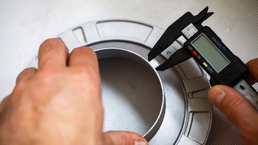
A small dimensional change made after a steel die has been hardened can require costly die rework—or, in some cases, a replacement tool. For this reason, it is important to validate the part geometry, material specification, critical radii, tolerances, and functional requirements as thoroughly as possible before hard tooling is released for manufacture.
Before cutting production tooling at ShincoFab, our engineering team uses finite-element sheet-metal forming simulation to evaluate how the specified material is likely to behave during stamping or deep drawing. The simulation models factors such as part and tool geometry, material properties, press forces, and friction, then predicts the resulting stress, strain, thinning, and material flow.
We review the simulation results for potential forming risks, including localized thinning, splitting, wrinkling, and springback. Where a high-risk area is identified, we can refine key design and process variables—such as draw radii, blank geometry, material thickness, or forming stages—before committing to hardened production tooling. Forming Limit Curves (FLCs) provide an engineering basis for this evaluation by showing the strain levels at which sheet metal may begin to neck or fail.
How to Fix Common Deep Drawing Defects (The ShincoFab Way)
Troubleshooting Wrinkles and Tears
Even with perfect software simulation, reality on the press is different. The two most common problems we fix during a die tryout are flange wrinkling and bottom tearing. Both usually come down to Blank Holder Force (BHF).
If the blank holder applies too little pressure, the metal pulls in too fast and bunches up, causing wrinkles. If it applies too much pressure, the material is locked in place and the punch just stretches it until the bottom tears out.
When I see a tear at the punch radius on the floor, it usually means the blank holder pressure is too high or lubrication is failing. Dropping the nitrogen gas spring pressure by just 5% to 10%, or switching to a heavy-duty drawing compound, often solves the issue instantly.
Conclusion
Deep drawing is a powerful manufacturing tool for strong, seamless, high-volume parts. If your annual volume justifies it, this process will significantly reduce your per-part costs.
Are you ready to see if deep drawing fits your next project? Reach out to the engineering team at ShincoFab today. Send us your CAD files, and we will run the simulation, calculate your tooling ROI, and help you make the smartest choice for your budget.