At ShincoFab, our quality control bins have seen thousands of parts hit the scrap pile because of a single badly designed hole. As a lead fabrication engineer who spends every day walking between our CAD department and the ShincoFab factory floor, I know firsthand that countersink design is where most engineers make their most expensive mistakes. Fundamentally, countersink design is the process of calculating the precise major diameter, minor diameter, and cone angle required to allow a flathead fastener to sit flush with a material’s surface.
If you want your flathead screws to sit flush without tearing your sheet metal or blowing your manufacturing budget, you are in the right place. In this guide, I will share how we design and process countersinks that actually work in the real world. We will cover the exact measurements you need, how to prep your files for our machines, and how to avoid the hidden traps we see ruin parts frequently. Stop guessing your dimensions. Let’s get your hardware fitting exactly right.
The Golden Rule of Hardware-First Design
A Countersink is a Mating Surface
Let’s get one thing straight before you open any CAD software. A countersink is not just a hole. It is a mating surface.
Last quarter, a client sent ShincoFab a batch of 1,000 aluminum enclosures. They designed the holes first and bought the screws later, guessing the metric cone angle. The screws sat proud by 1mm, snagging on their internal components. We had to scrap the entire batch. It is highly recommended to have the exact screw in your hand, or the exact spec sheet on your screen, before you start drawing.
Why? Because flathead screws are incredibly picky. Flathead screws require exact specifications for three main reasons: varying cone angles, differing head diameters, and strict fitment tolerances.
- Angles change: Metric and Imperial screws use significantly different cone angles.
- Heads vary: The top diameter of a screw changes depending on the brand and size.
- Fitment fails: If you guess the size, your screw will likely stick out and catch on things, or sink too deep and weaken the metal.
As a best practice, pick your hardware first. Build the hole around the screw, not the other way around.
What is a Countersink?
Before diving into the exact dimensions of your chosen hardware, it helps to understand the fundamental geometry we are trying to create.
Countersink vs. Counterbore
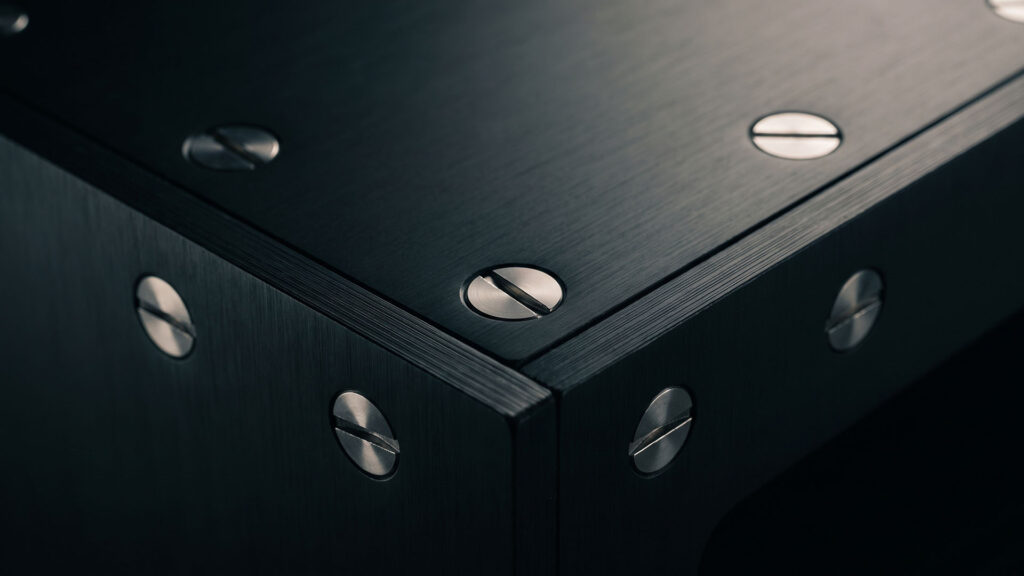
A countersink is a conical hole cut into a part. It allows a flathead screw to sit fully flush with the surface. People often confuse it with a counterbore. The simple difference is that a countersink has a sloped, cone-shaped bottom, whereas a counterbore has a flat bottom made for standard socket-head bolts.
Why Use Them?
Why go through the extra effort to cut a cone into your metal? It comes down to performance and looks. The three main advantages of using a countersink in sheet metal are flush surfaces, improved safety, and self-aligning assembly.
- Flush surfaces: Hardware is kept out of the way to avoid catching on clothing or moving parts.
- Safety: You remove sharp screw heads from the user’s reach.
- Self-aligning: The cone shape forces the mating parts to center precisely as you tighten the screw.
Let’s look at a real-world example from our shop floor. In a recent custom server rack project we ran at ShincoFab, standard protruding screw heads were causing hard crashes on the sliding rail assemblies. By switching to countersinks, we saved exactly 0.15 inches of clearance, allowing the rails to glide smoothly without jamming.
What Are the Key Measurements for Countersink Design?
To achieve the optimal flush fit and clearance mentioned above, you have to get the math right. Fortunately, to make a countersink work, you primarily need to focus on three numbers.
Major and Minor Diameters
The major diameter is the diameter at the top opening of the countersink. It must be sized for the specified fastener head diameter and countersink angle so that the selected flat-head screw seats flush with the sheet surface. The minor diameter, also called the pilot or clearance-hole diameter, is the straight hole below the conical countersink. It must provide sufficient clearance for the screw shank and threads to pass through without interference.
Based on the tooling we use daily at ShincoFab and the fit classes specified in ASME B18.2.8 clearance-hole recommendations, the table below lists the recommended minor clearance-hole diameter and the corresponding major countersink diameter for three commonly used imperial flat-head screw sizes. Always verify the countersink angle and actual head dimensions against the applicable fastener specification before production.
| Screw Size | Minor Diameter (Clearance) | Major Diameter (Top Hole) |
|---|---|---|
| #8 | 0.177″ | 0.359″ |
| #10 | 0.201″ | 0.411″ |
| 1/4-20 | 0.266″ | 0.531″ |
Picking the Right Angle
The final measurement is the included angle of the countersink cone. This value must match the specified fastener head geometry; it should never be selected by guesswork or based on the measurement system alone.
For example, ASME B18.3 socket flat-head cap screws commonly use an 82° included angle in inch-series applications. ISO 2009 slotted countersunk flat-head screws use a 90° included angle in metric applications. In aerospace work, 100° countersunk-head rivets are widely used where a flush external surface is required; use 120° only when the applicable drawing, rivet specification, or customer standard explicitly calls for it.
- 82°: Common for inch-series flat-head socket cap screws made to ASME B18.3.
- 90°: Common for metric countersunk flat-head screws made to ISO standards, including ISO 2009.
- 100°: Common for aerospace flush-head rivets and certain aerospace fasteners.
- 120°: A special-purpose angle that must be verified against the applicable fastener specification or engineering drawing.
Before machining, confirm the screw or rivet head angle, head diameter, applicable standard, and required flushness condition from the fastener datasheet or the customer’s engineering drawing.
How Are Countersinks Made?
Once you have calculated your three core measurements, you need to determine how the hole will be physically created on the factory floor.
Machined vs. Formed Countersinks
There are two ways to put a countersink into sheet metal. You can machine it, or you can form it. You need to know which one your factory is using because it changes your design and your bill.
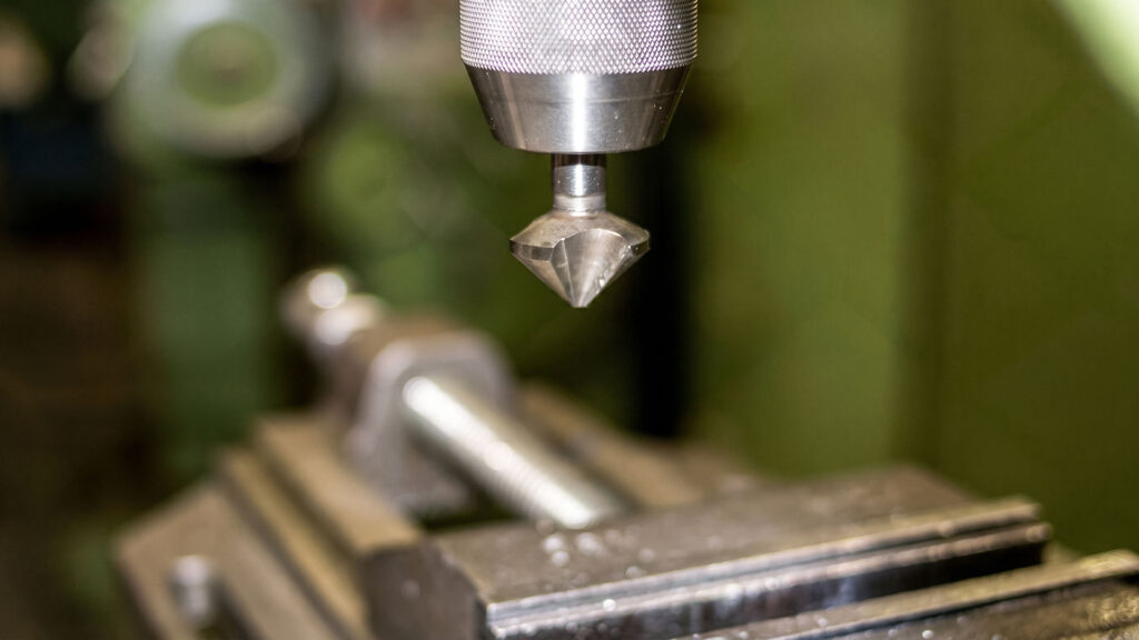
Machined countersinks are cut with a spinning tool on our 3-axis mills. The bit physically removes metal to create the cone. This method is great for thick parts or low-volume prototypes.
Formed countersinks are punched. At ShincoFab, we use our Amada CNC punch presses to squeeze the metal into a die. It bends the material into a cone shape without removing any metal at all. This is the best choice for thin sheet metal.
The Cost Factor: Forming on our CNC punch press takes about 1 second per hole, while our CNC mill takes 15 seconds to cut it. On a 500-part run with four holes each, specifying a formed dimple saves our clients roughly $250 in machine time.
How to Design a Countersink (Step-by-Step)
Whether your factory uses a CNC mill or a punch press, the actual design workflow in your CAD software follows the same critical path.
Step 1: Pick Your Fastener First
Remember our golden rule. Pull up the spec sheet for your fastener. Find the exact head diameter and cone angle.
Step 2: Check Material Thickness & Avoid the “Knife-Edge”
Our CAM engineers reject designs frequently because of this. If your countersink depth is the exact same thickness as your sheet metal, you create a weak knife edge. The bottom of the hole becomes razor-thin. When you tighten the screw, the metal is highly likely to tear.
The ShincoFab rule of thumb is that for an 82° screw, your sheet metal should be at least 0.030 inches thicker than the screw head depth to prevent this knife edge.
Step 3: Keep Away from Edges and Bends
If you put a hole too close to a bend line, our press brakes will distort the hole into an ugly oval as the metal stretches. Generally, keep the center of your countersink at least three times the material thickness away from any edge or bend.
Prepping Your CAD Files for the Manufacturer
Even a flawlessly modeled 3D design can be ruined if the 2D manufacturing files are exported incorrectly.
Exporting Clean Files
When customers upload 2D DXF files to the ShincoFab portal, this is where things often go wrong.
When you look at a countersink from the top down in CAD, it shows two circles. The inner circle is the through-hole. The outer circle is the major diameter. It is essential to delete that outer circle before you export your DXF.
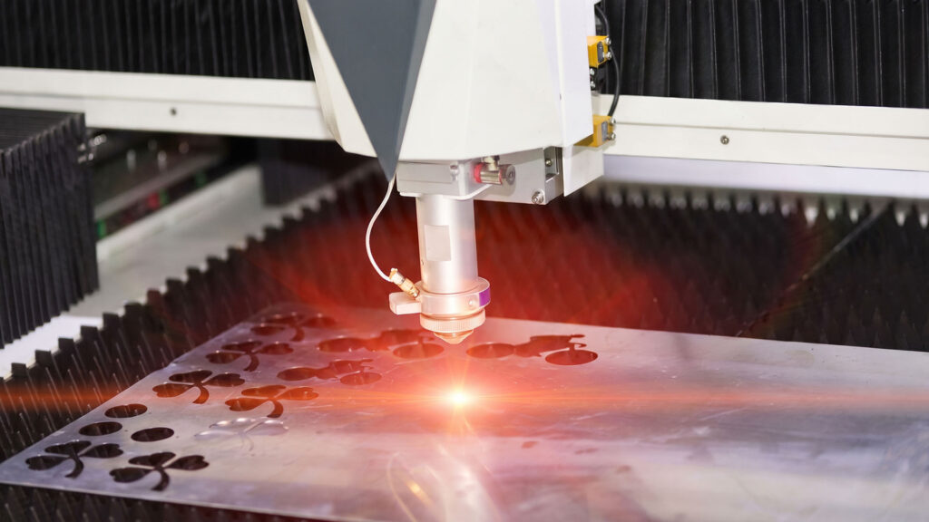
If you leave it, our laser cutters will trace the larger circle, which can compromise the hole. We’ve found that leaving the major diameter line in a DXF causes the laser to cut the hole too big 85% of the time. Make it a habit to delete the outer circle.
Common Countersink Mistakes (And How to Fix Them)
Clean DXF files will get your part cut accurately, but physical manufacturing and finishing introduce a whole new set of real-world variables.
The Screw Sticks Out (The Coating Dilemma)
You designed the hole accurately, but after finishing, the screw sticks out. What happened? The coating buildup was not included in the countersink design.
Powder coating film thickness is typically measured in mils, where 1 mil equals 0.001 in. Because the actual dry-film thickness varies by coating system and specification, do not assume a fixed allowance. If coating builds up on the countersink face, the available major diameter becomes smaller and a flat-head screw may sit proud of the finished surface.
If the part will be powder coated, painted, or anodized, slightly oversize the countersink based on the specified maximum finish thickness, or mask the countersink when a flush screw head is required.

Chatter Marks & Tear-Out
If you look inside the cone and see rough, wavy lines, you have chatter marks. This means the cutting tool vibrated at the machine. If the bottom edge looks ripped, you have tear-out. This indicates that your metal was too thin for a machined cut, and you should have asked us for a formed dimple instead.
How Can You Cut Costs on Countersunk Parts?
While avoiding the mistakes above will naturally protect your budget, there are proactive design choices you can make to reduce your manufacturing bill even further.
Standardize Your Sizes
Avoid using an 82° hole on one end and a 90° hole on the other. Whenever the angle changes, our machinists have to stop the CNC, swap the tool, and re-zero. Pick one screw style and use it everywhere.
Skip the Cut, Use a Dimple
If you are working with thin sheet metal, ask us to use a dimple die. It is faster, cheaper, and often stronger than cutting.
Only Countersink One Side
Try to keep all your countersinks on the top face. If you put holes on both sides, the machinist has to unclamp the part, flip it over, and set it up again. At ShincoFab, flipping a part requires a second setup. Depending on the part’s complexity and your batch size, this secondary operation can typically add anywhere from $50 to $150 in setup fees to your total run cost.
Bonus Tips for Prototyping Countersinks in 3D Printing
While ShincoFab specializes in metal fabrication, many of our clients prototype their designs in 3D printed plastic before bringing us the files for metal production. Plastic requires a different approach. To successfully 3D print countersunk prototypes, you must follow three essential rules including avoiding internal supports, accounting for plastic shrinkage, and using teardrop shapes on vertical walls.
- Ditch the Supports: Avoid placing support material inside your countersink cone. It is a nightmare to remove and ruins the flush fit.
- Account for Shrinkage: Plastic shrinks. If you draw a 5mm hole, it might print at 4.8mm. Add an extra 0.2mm to your minor diameter.
- The Teardrop Trick: If printing a hole on a vertical wall, gravity will cause the top to sag. Change the hole shape to a teardrop so the pointed top supports itself.
Conclusion
Designing a countersink does not have to be a guessing game. If you remember the golden rule of picking your hardware first, you are already ahead of most designers.
At ShincoFab, we want your parts to succeed on the first run. Consistently verify your material thickness, clean up your DXF files by removing the major diameter circle, and standardize your hardware to save costs. Stop leaving fitment to chance. Lock in your dimensions, and let’s get your parts manufactured right the first time.