If you design sheet metal parts, treating a bend relief like just another boring CAD rule is a costly mistake.
Here at ShincoFab, our press brake operators bend thousands of parts every single week. After years of manufacturing sheet metal on the shop floor, I’ve seen what happens when designers ignore bend reliefs or size them wrong based solely on textbook formulas. Parts tear, holes warp, and expensive metal goes straight into our scrap bins. You need to design your bend reliefs for the actual shop floor, not just the CAD screen.
In this guide, I will show you how we manage this at ShincoFab. You will learn the simple math to size your reliefs, the best shapes to use, and how your material choice changes your approach. I will also break down the three most common design mistakes that we actively flag during our DFM (Design for Manufacturing) reviews.
By the end of this article, you will know how to design parts that bend accurately the first time on our machines, saving you money and manual rework.
What Is a Bend Relief?
The Simple Definition
A bend relief is a small, intentional cut made right at the edge of a bend line.
Think about folding a piece of paper. If you try to fold just the middle inch of a page, you can’t. The rest of the paper crumples. But if you cut two small slits on either side of that middle inch, it folds cleanly.
This is primarily what a bend relief does for sheet metal. It separates the metal you want to bend from the metal you want to keep flat.
Bend Relief vs. Corner Relief
Our engineers frequently use these two terms. They do the same fundamental job, but in different places.
- Bend relief: This is used on a single bend that sits right next to a flat edge.
- Corner relief: This is used where two or three bends meet up. Think of the inside corners of the custom electronic enclosures we frequently build.
Both cuts remove enough material so the metal can take shape without tearing.
Why You Should Care About Bend Reliefs (The Real Cost of Ignoring Them)
What Happens When a Bend Fails
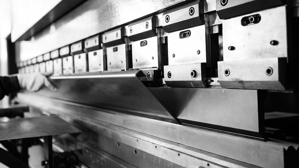
When we bend metal on our Amada press brakes, the outside stretches and the inside compresses. If that compressed metal has nowhere to go, it forces its way out. I have stood next to the machine and heard the sharp ping of 6061 aluminum micro-fracturing because a client forgot a relief. The metal might tear, or it might bow the flat flange right next to the bend, distorting your straight edge.
The True Cost of a Missing Relief
Forgetting a bend relief can noticeably impact your production budget. In severe cases, the part must be scrapped entirely. Other times, it requires one of our finishing technicians to spend 15 to 20 minutes or more manually grinding down the warped edge to make it flat again. That unplanned manual labor eats directly into your profit margins.
In the ShincoFab shop, missing or undersized bend reliefs used to account for roughly 14% of sheet metal part rejections during early prototyping. Before we implemented strict DFM checks, these rejections often resulted in unexpected costs averaging around $450 per prototyping batch, due to wasted material and redundant setup time.
Protect Holes and Cutouts
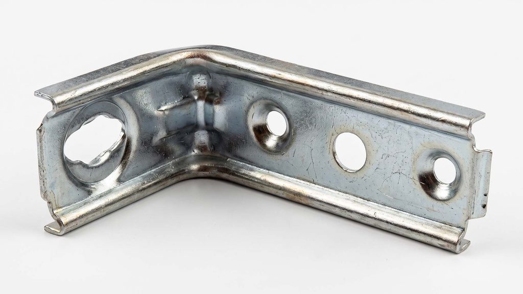
Bending creates a massive amount of stress. If you have a hole or a cutout too close to the bend line, that stress will pull it out of shape. We recently had a client whose round mounting holes became ovals because they lacked a relief shield; suddenly, their standard M4 screws wouldn’t fit.
A bend relief isolates that bending stress, keeping your nearby features dimensionally stable.
When Do You Actually Need a Bend Relief?
Bending Only Part of an Edge
You don’t always bend the whole piece of metal. Sometimes you just need a small tab bent up in the middle of a flat edge. If a bend doesn’t go all the way across the metal, you need a relief. Without it, our press brake’s tonnage can tear the metal right where the bend stops and the flat edge begins.
Meeting in the Corners
Think about building a metal tray or a box. You have flanges folding up on multiple sides. If you don’t cut away the corners, those flanges will crash into each other as they fold up. A corner relief removes that extra material so the edges can align properly without our operators having to force them.
When You Can Skip Them
You can save time by skipping reliefs on full-width bends. If we are bending the entire edge of a sheet from one side to the other, there is no flat material left behind to tear. You generally do not need a relief here.
How Your Material Choice Changes Your Bend Relief
Less Formable vs. More Forgiving Metals
Not all metals bend the same way. If you treat soft steel and hard aluminum as if they are identical, you risk damaging expensive parts.
Less formable materials, such as 6061‑T6 aluminum, are more prone to cracking during tight bends because the T6 temper provides relatively high strength with limited elongation. We frequently see this at ShincoFab. To reduce the risk of cracking on the press brake, you typically need a larger inside bend radius and properly sized bend reliefs. This gives the material more room to deform without concentrating excessive strain at the bend.
On the other hand, lower-carbon steels such as ASTM A36 structural steel are generally more forgiving in forming applications. Their comparatively higher ductility often allows tighter bends and smaller reliefs without tearing the part. However, actual bend performance still depends on material thickness, grain direction, rolling condition, bend angle, and tooling. Always verify the applicable material properties and bend-radius requirements before finalizing your design.
How to Size Your Bend Reliefs (The Math & The Tooling Reality)
The Basic Math (Width & Depth)
Sizing a bend relief typically requires two simple rules.
- Width: Your relief width should be at least half the thickness of your material.
- Depth: Your relief depth needs to fully clear the bend. The formula is: Material Thickness + Bend Radius + a tiny bit of clearance (usually 0.02 inches).
How Press Brake Tooling Changes the Game
Most CAD tutorials miss a crucial secret that our machine operators wish every engineer knew. The factory’s actual press brake tooling dictates the final result.
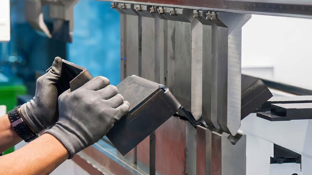
When our machine bends metal, it presses the sheet into a V-shaped die. That V-die has a specific width. If your bend is too close to a flat edge, the flat metal may fall into the die and bend crooked. Because of this, your relief might actually need to be larger than the basic math suggests to clear our standard V-dies.
The ShincoFab Shop Floor Cheat Sheet
Here is the standard cheat sheet our factory uses to size reliefs for three common materials we process daily:
| Material | Thickness | Min Relief Width | Min Relief Depth |
|---|---|---|---|
| Mild Steel | 0.048″ (18 ga) | 0.030″ | 0.070″ |
| 5052 Aluminum | 0.063″ (16 ga) | 0.040″ | 0.090″ |
| 304 Stainless Steel | 0.120″ (11 ga) | 0.080″ | 0.150″ |
What is the Best Bend Relief Shape?
Round and Obround (The Best Choices)
When it comes to bend reliefs, curves are highly effective. Round and obround shapes are the top choices because they stop stress from building up in one spot.
Based on our internal stress tests at ShincoFab, a round relief handles nearly 3 times more vibration than a sharp square relief before micro-fracturing. Plus, an obround relief takes our Trumpf fiber lasers just 0.4 seconds to cut, making it highly efficient for your production run.
Rectangular (Use with Caution)
You can use rectangular reliefs, but you need to be careful. Sharp, square corners create concentrated weak points in the metal. If your part takes a heavy load, those sharp corners are often where cracks begin to form.
The Tear Option (Avoid This)
Many CAD programs offer a specific relief shape known as a Tear. We strongly advise against using it.
This setting tells the software to make a zero-width slice in the metal. That looks fine on your screen, but in our factory, cutting tools have a physical width. Even our highly focused laser has a kerf of about 0.006 to 0.008 inches. If you design a zero-width cut, our CAM software will likely flag it, requiring us to pause your order to fix the file.
Balancing Gaps and Costs in Welding and Waterproofing
Sealing Your Enclosures
If you are building an IP-rated enclosure, you face a unique design challenge: a bend relief intentionally creates an opening in the sheet metal, which can become a potential path for dust or water ingress.
To address this, the relief gap may need to be continuously welded or otherwise sealed after the metal is bent, depending on the required IP rating and enclosure design. Our recommended approach at ShincoFab is to use a tight obround bend relief. This shape minimizes the open area and leaves a smaller, more manageable gap for welding or seam sealing.
For critical sealing applications, confirm that the final weld or seal is continuous and validate the completed enclosure against the applicable ingress-protection test requirements.
The Cost of Welding Bad Reliefs
A poor relief design can significantly inflate your post-processing budget.
Our lead TIG welder at ShincoFab can fuse a tight 0.015-inch obround gap in just 12 seconds without adding wire. If you use a massive square relief instead, it takes him roughly 3 times longer just to fill it with a filler rod. When factoring in the additional welding time, consumed filler material, and the mandatory post-weld grinding required to smooth out the larger weld bead, that simple CAD mistake can drive up your total processing cost by an estimated $2.50 to $4.00 per corner.
How to Add Bend Reliefs in Your CAD Software
You do not need to draw every bend relief by hand. Modern CAD programs include sheet-metal tools that can apply reliefs automatically according to the manufacturing rules you define.
Follow these three steps to add bend reliefs in CAD software such as Fusion’s Sheet Metal Rules and Bend tools or SolidWorks.
- Set Your Sheet Metal Rules. Enter the actual material thickness, bend radius, and other forming parameters so the flat pattern reflects your intended manufacturing process.
- Define the Relief Shape. Select the relief style and set its width and depth according to your part geometry and our ShincoFab cheat sheet. In SolidWorks, Corner Relief options can include circular and obround configurations, among other relief types.
- Use the Flange or Bend Tool. When bend relief is enabled in Fusion, the software can automatically apply a relief where required; you can also override the rules for individual bends when the design needs a different result.
What are the Most Common Bend Relief Mistakes?
Here are the three most common design errors our DFM engineers flag at ShincoFab:
Mistake 1: Making the Relief Too Shallow
This is a frequent error. If your relief isn’t deep enough, the press brake will force the metal to bend, often ripping the adjacent flange to do it.
The Fix: Double-check your depth math. Make sure the cut extends fully past the bend radius and slightly into the flat material.
Mistake 2: Putting a Hole Too Close to the Relief
We often see small brackets where a mounting hole is dropped right next to a bend relief. The bending force can easily turn a round hole into a warped oval.
The Fix: As a general practice, move holes at least two to three times the material thickness away from the bend line.
Mistake 3: Forgetting the Laser’s Kerf
If you design a relief that is exactly the bare minimum width, our laser’s kerf (cutting width) might alter that space and make the relief too tight to work properly.
The Fix: Add a tiny bit of clearance to your design. Tacking on an extra 0.02 inches helps ensure ShincoFab can cut it cleanly and bend it safely.
Conclusion
A properly designed bend relief is your best defense against torn metal, warped holes, and blown budgets on the shop floor.
Remember these key takeaways before you send your next step file to ShincoFab.
- Do the math: Make your relief width at least half your material thickness.
- Choose curves: Stick to round or obround shapes to help keep welding costs low.
- Know your metal: Give brittle materials like 6061 aluminum more room to bend.
When you design for the real world, your parts are much more likely to be manufactured accurately the first time. We save you money, minimize scrap, and keep your production running smoothly.
Frequently Asked Questions (FAQ)
Can I use a zero-width tear for a bend relief?
It is not recommended. While a tear looks fine on a CAD screen, real-world cutting tools like lasers have a physical width (kerf) of roughly 0.006 to 0.008 inches. Designing a zero-width cut often causes CAM software errors and halts manufacturing. We suggest using a small, physical width, such as an obround shape.
How close can a hole be to a bend line?
As a general rule, a hole should be placed a minimum distance of two to three times the material thickness away from the bend line. Placing a hole too close without a proper relief often causes the bending stress to warp the hole into an oval, preventing fasteners from fitting correctly.
Does mild steel need a different bend relief than aluminum?
Usually, yes. Mild steel (like A36) is highly malleable and forgiving, allowing for smaller, tighter bend reliefs. Aluminum (especially 6061-T6) is more brittle and prone to micro-fracturing under bending stress. Brittle materials typically require wider, rounded bend reliefs to give the metal enough room to stretch without cracking.