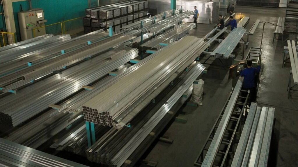
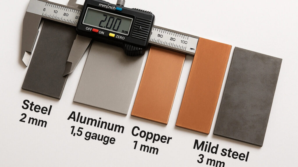
Here at ShincoFab, I’ve spent years on our sheet metal fabrication floor watching great welders make expensive mistakes simply because they misread a blueprint. Whether we are fabricating custom 16-gauge stainless steel enclosures or heavy-duty aluminum chassis, I know exactly how frustrating it is to translate complicated engineer-speak into real-world welding.
In this guide, I will show you how to read weld symbols quickly and accurately. You will learn how to decode the lines, shapes, and numbers without needing an engineering degree.
By the end of this article, you will have a simple mental checklist to read any blueprint with high confidence. You will know how to avoid costly rework, stop wasting expensive filler metal, and protect your shop’s profit margins. Let’s get straight to it.
Quick 3-Step Shop Floor Checklist
Standing on the shop floor with a blueprint right now? Use this quick system to decode the symbol before you strike an arc. (We cover the details of each step further down).
- Find the Arrow (Location): Follow the arrow to the joint. If the symbol shape is below the reference line, weld exactly where the arrow points. If it sits above the line, weld the opposite side.
- Check the Shape (Weld Type): A triangle means a fillet weld. A “V” or “U” means a groove weld. A circle at the corner means weld all the way around the joint.
- Read the Numbers (Size & Spacing): Look to the left of the shape for your exact weld size. Look to the right for length and spacing (pitch). Never guess the size!
What Are Weld Symbols (And Why Should You Care?)
The Universal Language of Welding (And Why It’s a Financial Contract)
Weld symbols are graphical representations used on blueprints to instruct welders on how to join two pieces of metal. They dictate the weld type, size, location, and required processing to ensure structural integrity. Beyond being a simple geometry lesson, these symbols act as a strict financial contract.
When an engineer puts a symbol on a drawing, they are telling you exactly what the customer is paying for. If you guess, you risk the shop’s profit margin. Just last year at ShincoFab, a misinterpreted symbol on a custom NEMA enclosure order meant we had to scrap an entire pallet of precision-cut sheet metal. That one mistake wiped out the profit margin for the whole project.
How Reading Symbols Saves You Time and Money
Guessing is expensive. Many welders mistakenly believe that larger welds equal stronger joints and add extra metal to be safe. This is a huge mistake, especially in sheet metal fabrication.
Over-welding wastes expensive filler metal. It burns through shielding gas. It also takes way more time. Worse, too much heat can warp the metal and ruin the part, which creates a massive headache when you are dealing with thin materials like the 14-gauge sheets we process daily.
Let’s look at the real cost. According to the American Society for Quality, the cost of poor quality—including rework, scrap, and waste can include the correction of defective materials or errors, as well as unnecessary work and unusable material caused by mistakes or poor communication. Misreading blueprints can contribute to exactly these types of internal failure costs. When you know how to read these symbols correctly, you help protect both your paycheck and the shop’s bottom line. Mastering this skill benefits you directly in several ways.
- You avoid rework: No more grinding out bad welds (which often destroys thin sheet metal anyway).
- You save materials: You stop wasting expensive filler wire and gas.
- You build trust: You get the job done right the first time.
Before reading any symbol, you must identify which language the blueprint is speaking. The rules change significantly depending on your customer’s location.
Are You Reading an AWS or ISO Standard?
You cannot read a book if you do not know the language. The same goes for blueprints. Before you strike an arc, you need to know which rulebook the engineer used.
The American Standard (AWS A2.4)
If you work with welding drawings in the United States, you will commonly encounter the AWS system. AWS stands for the American Welding Society. Its AWS A2.4:2020 Standard Symbols for Welding, Brazing, and Nondestructive Examination is an American National Standard that establishes a method for communicating welding, brazing, and nondestructive examination requirements through standardized symbols.
The AWS system uses a solid reference line. Information placed below the reference line applies to the arrow side of the joint, while information above the line applies to the other side. Once you understand this convention, AWS welding symbols become much easier to interpret consistently.
The International Standard (ISO 2553)
Because ShincoFab regularly partners with European clients on custom sheet metal components, our welders frequently encounter drawings based on ISO conventions. The governing standard, ISO 2553:2019 — Welding and allied processes: Symbolic representation on drawings — Welded joints, defines rules for representing welded joints on technical drawings, including information about weld geometry, manufacture, quality, and testing.
ISO 2553 recognizes two symbol systems used internationally. System A uses a dual reference line: a continuous line and a dashed line distinguish the arrow side from the other side of the joint. System B uses a single reference line, similar to the convention commonly used in AWS drawings. Before interpreting any ISO weld symbol, confirm which system the drawing specifies. Misreading the reference-line system can lead to welding the wrong side of the part.
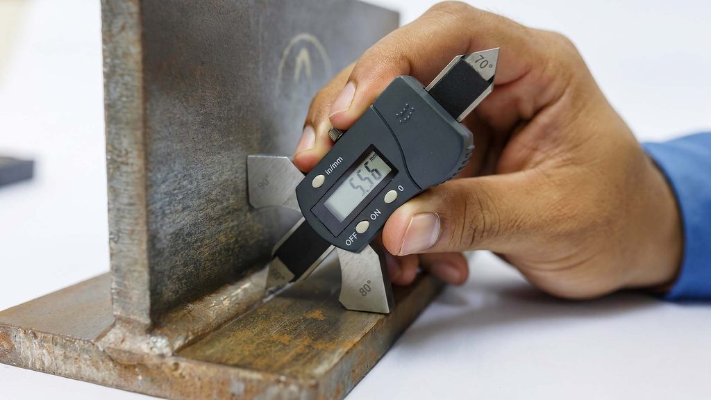
How a Foreman Can Spot the Difference Quickly (Decision-Making Guide)
A good foreman checks the standard before handing a blueprint to a welder. You never want to find out you used the wrong system after the part is already built. In fact, global quality control data shows that** mixing up the AWS solid line and the ISO dashed line causes over 30% of all international manufacturing weld errors.
You can spot the difference in two seconds by checking a few quick details.
- Look for the dashed line: If you see a dashed line sitting right below the main solid line, you are looking at an ISO drawing.
- Check the title block: Look at the bottom right corner of the blueprint. The engineer explicitly lists the AWS A2.4 or ISO 2553 standard right there.
- Check the measurements: Are the weld sizes in inches or millimeters? When we receive metric drawings at ShincoFab, it’s an immediate red flag for our team to double-check if we’re dealing with an ISO standard.
Every weld symbol is built on the exact same foundation. Once you verify the standard, you only need to break down three basic components.
The Anatomy of a Basic Weld Symbol
Think of a weld symbol like a skeleton. It has three main bones. Once you know these three parts, the rest is filling in the blanks.
The Reference Line (Your Starting Point)
Everything starts with the reference line. It is the horizontal line in the middle of the symbol. Think of it as an anchor. Every piece of information about the weld sits on this line. This includes the size, the shape, and the length. If you take away the reference line, the rest of the symbol falls apart.
The Arrow (Pointing to the Joint)
At one end of the reference line, you will find an arrow. This arrow points to the joint that needs welding. It acts as a giant directional marker guiding you to the exact spot. The arrow can point up, down, or sideways. The direction does not matter. Its primary job is to show you which two pieces of metal need to join.
The Tail (Special Instructions)
At the opposite end of the arrow, you might see a V-shaped tail. This part is optional. Engineers use the tail to give you special instructions. This section typically contains a few specific requirements.
- The welding process: It might specify TIG or MIG welding so you know which machine to set up.
- The filler metal: It might require a specific electrode such as the E7018.
- Inspection rules: It might tell you the weld needs an X-ray or ultrasonic test.
If the weld is standard and needs no special rules, the engineer will leave the tail off.
The tricky part is that just because the arrow points to a joint does not mean you weld on that exact side. Location is directly determined by where the symbol sits on the reference line.
How to Get the Location Right for Arrow and Other Side Welds
Knowing where the joint is located is only half the battle. You also need to know exactly which side of the metal gets the weld.
Symbols Below the Line (Arrow Side)
Look at the reference line. Is the weld shape drawn below it? If yes, you are looking at an arrow side weld. This means you put the weld where the arrow is pointing. You do not flip the part. You do not walk around to the back. You weld right at the tip of the arrow.
Symbols Above the Line (Other Side)
Now, look above the reference line. If the weld shape is sitting on top of the line, you have an other-side weld. This means the arrow points to the joint, but you must weld on the opposite side of that joint. You will need to flip the metal over or walk around to the back of the part to do the work.
Symbols on Both Sides
Sometimes, you will see shapes both above and below the reference line. This is a double-sided weld. You must weld the arrow side, then flip the part and weld the other side. You interpret these symbols based on how they align with each other.
- Symmetrical: If the shapes line up perfectly, both welds go in the exact same spot on opposite sides.
- Staggered: If the shapes are offset from each other, your welds will be staggered along the joint.
The Structural Failure Mode of Confusing the Sides
Confusing the arrow side with the other side is a massive mistake. It is not just a cosmetic issue. It causes catastrophic structural failures.
Engineers design parts to handle specific working loads. If you weld the wrong side, the joint rarely handles its intended stress. The most common failure is known as the hinge effect. When weight pushes on the part, the unwelded side pulls open like a door hinge. In sheet metal brackets, this means the bracket is highly prone to tearing away from the main chassis under load. The metal cracks, the part fails to meet specifications, and the shop pays for the ruined material.
Common Types of Weld Symbols You Will Use
The most common weld symbols used in metal fabrication include the fillet (triangle), groove (V, U, bevel, J), plug (rectangle), and spot (circle) welds. The comparison table below breaks down these standard weld shapes, their matching blueprint symbols, and their real-world joint applications.
| Weld Type | Symbol Shape | Common Joint Application |
|---|---|---|
| Fillet Weld | Right Triangle | T-joints, lap joints, and corner joints (joining metal at an angle) |
| V-Groove | “V” Shape | Edge-to-edge joints (both metal edges cut at an angle) |
| Bevel Groove | Single Angle | Edge-to-edge joints (one edge angled, one left square) |
| U/J-Groove | “U” or “J” Shape | Edge-to-edge joints (edges scooped out) |
| Plug & Slot | Rectangle | Overlapping plates (filling a round or oval hole) |
| Spot Weld | Simple Circle | Fusing thin overlapping metals at a single point |
| Seam Weld | Circle with two parallel lines | Creating continuous, airtight seams on thin metal enclosures |
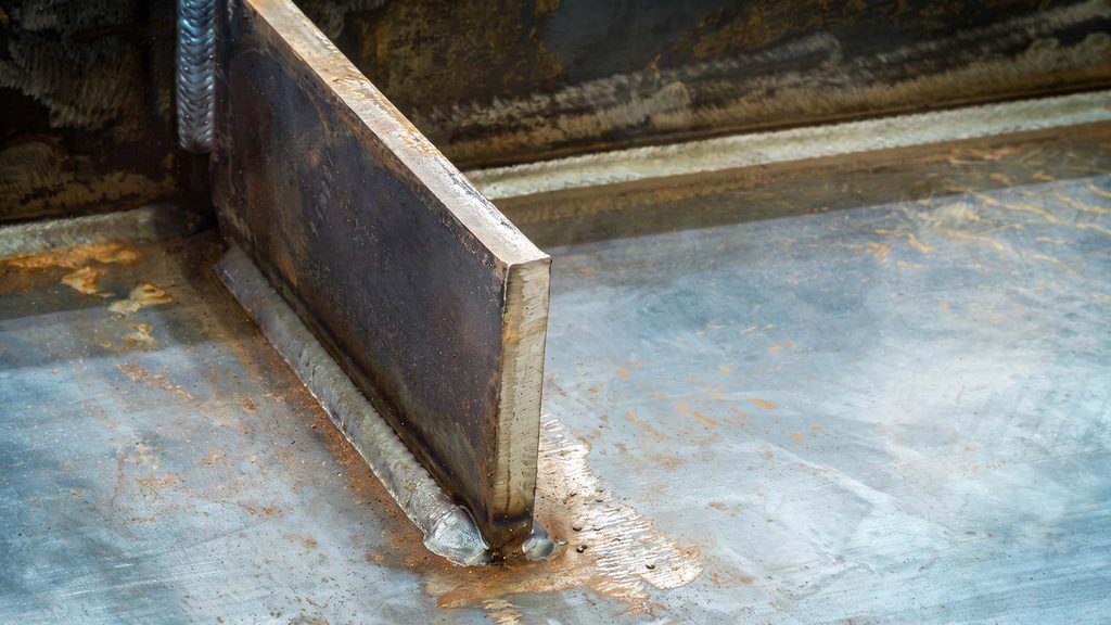
Fillet Welds (The Triangle)
The fillet weld is the most common symbol in the industry. As shown in the table above, it looks like a right triangle and is used to join two pieces of metal at an angle. No matter which way the arrow points, the straight, vertical line of the triangle is always drawn on the left side.
Groove Welds (V, Bevel, U, and J)
Groove welds are used when you join two plates edge-to-edge. The symbol matches the shape of the metal edges before you weld them.
- V-Groove: Both edges are cut at an angle to form a “V”.
- Bevel: One edge is cut at an angle. The other is left square.
- U-Groove: Both edges are scooped out to form a “U” shape.
- J-Groove: One edge is scooped out. The other is left square.
Plug and Slot Welds
You use these when you need to join two overlapping plates. One plate will have a hole cut into it. You fill that hole with weld metal to fuse the plates together.
- Plug Weld: The hole is perfectly round. The symbol is a rectangle.
- Slot Weld: The hole is long and oval-shaped. The symbol is also a rectangle, but it will have length numbers attached to it.
Spot and Seam Welds
Because we specialize in sheet metal fabrication at ShincoFab, spot and seam welds are our absolute bread and butter. We use these daily on our CNC spot welders to fuse thin metals together without filler wire, relying on heat and pressure instead.
- Spot Weld: A single point of heat.
- Seam Weld: A continuous line of spot welds, often used in our shop to create airtight seams for liquid-tight enclosures.
Decoding the Numbers on a Weld Symbol
The shape tells you what to do. The numbers tell you exactly how to do it. Reading these numbers correctly is the difference between a profitable job and a massive loss.
Weld Size and Penetration Depth
Look to the left of the weld symbol. This is where you find the weld size. For a fillet weld, this number tells you how long the legs of the triangle need to be. For a groove weld, you might see two numbers. The first is the depth of the groove itself.
The second number is in parentheses. That is the penetration depth. It tells you exactly how deep the weld metal must melt into the joint to be structurally safe.
Length and Pitch (Spacing)
Now look to the right of the symbol. This is where you find the length and pitch. You use these numbers for stitch welds, which are welds that are not continuous.
- Length: The first number tells you exactly how long each weld bead should be.
- Pitch: The second number comes after a dash. It tells you the distance from the center of one weld to the center of the next.
Angles and Root Openings
Groove welds require specific joint preparation. On a welding symbol, the dimensions associated with a V-groove or bevel-groove symbol communicate how the joint edges must be prepared before welding.
Root Opening: This dimension specifies the required gap between the two plates or members at the root of the joint before welding begins.
Groove Angle: This value specifies the included angle or bevel angle used to cut, machine, or grind the joint edges, depending on the joint design and drawing convention.
Reading these dimensions correctly is not only about passing inspection—it also helps control welding costs. As Lincoln Electric explains in its guidance on reducing welding costs by preventing overwelding, increasing a specified 1/4-inch fillet weld to 5/16 inch raises weld-metal volume from 0.129 lb to 0.201 lb per foot—an increase of approximately 56%. Oversized welds also require additional arc-on time, filler metal, shielding gas, and labor, while increasing the risk of heat distortion. A small increase in weld size may look harmless on paper, but across production volumes, it can significantly erode profit margins.
How Misreading Symbols Leads to Over-Welding (And Wastes Money)
Many welders ignore the numbers on the blueprint. They lay down a massive bead to “make it look strong.” This is called over-welding, and it is a terrible habit.
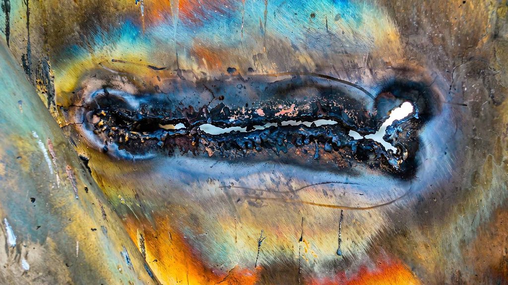
The Hidden Cost of Making Welds Look Strong (1/4-Inch vs. 3/8-Inch Welds)
Let’s compare a 1/4-inch fillet weld to a 3/8-inch fillet weld. The 3/8-inch weld is not just a little bit bigger. Because a fillet weld is a triangle, the volume of metal more than doubles.
When you guess the size instead of reading the symbol, you create a chain reaction of waste.
- Wasted Wire: You use twice as much filler metal.
- Wasted Gas: You burn through twice as much shielding gas.
- Wasted Time: It takes you twice as long to finish the joint.
- Massive Distortion: This is the silent killer at ShincoFab. Pumping excessive heat into a 16-gauge steel panel doesn’t make it stronger; it warps it like a potato chip. Once thin sheet metal distorts from over-welding, it is nearly impossible to flatten it back to spec, meaning the whole part goes straight into our scrap bin.
The numbers on the reference line protect your profits. However, complex joints often require extra processing instructions built around the core symbol.
Supplementary Symbols (The Extra Details)
Basic shapes and numbers give you the core instructions. But sometimes, a joint requires more work. Engineers use supplementary symbols to add these extra rules.
Weld All-Around (The Circle)
Look right where the arrow meets the reference line. Do you see an open circle? That is the weld-all-around symbol. It means you must weld the entire perimeter of the joint. You do not stop at the corners. You keep going until your weld meets your starting point.
Field Weld (The Flag)
Right next to that circle, you might see a little flag. This is the field weld symbol. It tells you not to weld the part in the shop. Instead, the parts will be shipped loose. The welding must happen on the actual job site during final assembly. If you weld it in the shop by mistake, the part will not fit on the truck.
Melt-Through and Backing Bars
For high-strength joints, engineers want the weld to penetrate all the way through the metal. They rely on the following two symbols to control this process.
- Melt-Through: This looks like a solid half-circle on the opposite side of the main weld symbol. It means the weld metal must push completely through the root of the joint.
- Backing Bar: This is a rectangle placed on the opposite side of the symbol. It tells you to place a strip of metal behind the joint before you weld. This stops the molten puddle from falling through the gap.
Finishing Symbols (Grinding, Machining, Chipping)
Sometimes a weld cannot stay bumpy. It needs to be ground flush so another part can fit over it. You will see a straight line above the weld shape, along with a specific letter. Each letter dictates a different finishing method.
- G (Grinding): Take a grinder and smooth the weld flush with the metal.
- M (Machining): The part will go to a mill or lathe to cut the weld flush / cut the weld precisely.
- C (Chipping): Use a pneumatic chisel to remove excess metal.
Memorizing a textbook on lines and shapes is unnecessary. To survive on the shop floor, you only need a fast, reliable mental framework.
The 3-Step Mental Checklist for the Shop Floor
You are standing on the shop floor. Your hood is up, and you have a blueprint in your hand. You do not have time to overthink. You need a fast, reliable system to decode the weld symbol before you strike an arc. Use this simple 3-step mental checklist every single time.
Step 1: Find the Arrow
First, figure out exactly where the weld goes. Follow the arrow to the joint. Now, look at the reference line. Is the symbol below the line? Weld exactly where the arrow points. Is the symbol above the line? Walk around to the other side of the part. Do not touch your torch until you are 100% sure you are on the correct side.
Step 2: Check the Shape
Next, look at the shape sitting on the reference line. This tells you what kind of weld to make.
- Is it a triangle? You are making a fillet weld in a corner or T-joint.
- Is it a V or a U? You are filling a groove between two plates.
- Is there a circle at the corner? You are welding all the way around the part.
Get the shape right in your head. This tells you how to prep the metal and angle your torch.
Step 3: Read the Numbers
Finally, check the numbers to the left and right of the shape. This is your financial contract. Look to the left for the size. If it says 1/4-inch, make it exactly 1/4-inch. Look to the right for the length. If it says to weld for two inches and skip four inches, follow that spacing strictly.
Do not guess. Do not add extra metal to be safe. Follow the numbers.
This 3-step checklist will keep you out of trouble most of the time, provided you avoid the trap of rushing.
Common Mistakes When Reading Weld Symbols
Even veteran welders make mistakes. When you are rushing to meet a deadline, it is easy to misread a symbol. But small mistakes on a blueprint lead to massive headaches on the shop floor. Here are the three most common errors you need to avoid.
Mixing Up the Arrow and Other Side
This is the number one mistake in fabrication. A welder sees an arrow pointing to a joint and immediately starts welding. They forget to check if the symbol is above or below the reference line. If the symbol is above the line, you must weld the opposite side. If you weld the arrow side by mistake, the part is ruined. You will spend hours grinding out the wrong weld to start over. Always pause and check the line.
Ignoring the Tail Instructions
The tail of the symbol sits at the far end of the reference line. Many welders ignore it because it is often empty. But when an engineer uses the tail, it contains critical rules.
- Wrong Process: The tail might specify TIG welding, but you used a MIG gun because it was faster.
- Wrong Wire: The tail might call for stainless steel filler, but you used mild steel.
If you ignore the tail, your weld will fail inspection. The inspector will make you cut it out, no matter how pretty the bead looks.
Guessing the Weld Size
We talked about this earlier, but it is worth repeating. Guessing the weld size destroys profit margins. If the symbol calls for a 3/16-inch weld, do not lay down a 5/16-inch weld.
You are wasting expensive wire and gas. You are also pumping unnecessary heat into the metal, which causes warping. Read the number on the left side of the symbol and stick to it.
Even with perfect reading skills, you will eventually encounter blueprints with smudged lines, missing numbers, or contradictory instructions.
What to Do When a Weld Symbol is Missing or Confusing
Engineers are human. They make mistakes. Sometimes blueprints get printed with missing numbers, smudged lines, or symbols that make zero sense.
Why Relying on Standard Shop Practice is a Dangerous Trap
When a size is missing, many welders shrug. They fall back on standard shop practice and lay down a weld that looks right. This is a massive trap. If that part fails in the field, the customer will look at the blueprint. If your weld does not match their specified requirements, your shop is liable. Never guess. If the drawing is wrong, stop working.
How to Submit an RFI (Request for Information) to Prevent Rework
At ShincoFab, our SOP (Standard Operating Procedure) is non-negotiable. If a symbol is missing or smudged, you do not strike an arc.
The correct move is to ask for help. Take the bad blueprint to your foreman or project manager. They will submit an RFI, which stands for Request for Information. We physically tag the un-welded part with red tape on our floor until the office gets the answer in writing from the engineer.
Yes, waiting for an answer slows down production temporarily. But guessing is much worse. Based on our own historical cost analysis at ShincoFab, a failed weld inspection that requires grinding out and re-welding typically costs between $500 and $1,000 per joint in wasted labor, materials, and machine downtime.
Waiting an hour for an RFI is consistently cheaper than grinding out a bad weld. Treat every weld symbol like a financial contract. Read it carefully, follow the numbers exactly, and ask questions when things look wrong. That is how you protect your shop’s profits and become a top-tier welder.
Conclusion
Reading weld symbols does not have to be a guessing game. Once you understand the basic anatomy, including the reference line, the arrow, and the tail, you can decode almost any blueprint that comes across your workbench.
Remember, these symbols are more than just instructions. They are financial contracts. Every time you check the standard, verify the arrow side, and stick to the exact numbers, you are protecting your shop from costly rework and wasted materials.
Keep that 3-step mental checklist in your back pocket. Find the arrow, check the shape, and read the numbers. If a blueprint ever looks wrong or is missing details, stop and ask. A quick question today is always cheaper than grinding out a bad weld tomorrow.