If you bend sheet metal, you know the frustration of folding a part only to find the dimensions are out of tolerance. As a lead fabrication engineer here at ShincoFab, I’ve spent years on the shop floor bridging the gap between CAD designers and press brake operators. I know how much money goes into the scrap bin because someone guessed a number instead of testing it.
That number is the K-factor.
In this guide, I will show you how to master it based on the daily protocols we use on our own factory floor. You will learn what the K-factor is, why you should verify your CAD software’s defaults, and how to calculate it without complex math. I will also show you how to test it on your own machines in just 12 minutes.
Why You Need to Get the K-Factor Right ?
Ignoring the K-factor hurts your bottom line. It also makes your shop floor a stressful place to work.
Stop Wasting Material on Scrap
Whenever your press brake operator bends a part that is out of tolerance, you throw money in the scrap bin. You paid for that metal. You paid for the laser time to cut it. You paid the operator to bend it.
Getting the K-factor right significantly increases your chances of bending the part correctly the first time. No more trial and error. No more cutting five extra blanks as a backup.
Assembly Line Complications
A bad K-factor doesn’t just ruin things at the press brake. It creates complications down the line.
Think about what happens when a flange is just a fraction of an inch too long. The problems multiply quickly:
- Stacked tolerances: One bad bend is annoying. Four bad bends on the same part means the final overall dimension is out of tolerance.
- Misaligned bolt holes: Your assembly crew has to break out the drills. They waste time widening holes just to make the bolts drop in.
- Weld fixture fights: Parts will not sit flat in your jigs. Your welders end up using heavy clamps and hammers to force pieces together.
The True Dollar Cost of a Bad K-Factor Guess
Leaving your CAD software at a default 0.33 or 0.5 K-factor is guessing. And guessing is expensive.
The Cost of Guessing: A Lesson We Learned the Hard Way
Let me give you a real-world example of what happens when you don’t test your metal. Before we implemented our strict testing protocols at ShincoFab, our shop ran an order for 10,000 steel mounting brackets.
The designer left the K-factor at the software default of 0.5. They didn’t test the actual tooling or the new batch of mild steel we had just received.
Here is what that single guess cost our business that day:
- The brackets came out 0.040″ too long.
- The mounting holes missed the mating parts on the assembly line.
- We scrapped 1,200 brackets before our floor manager caught the issue.
- The total loss: $3,400 in wasted steel and 18 hours of unpaid rework.
All of this happened because of one wrong number on a blueprint.
What Exactly is the K-Factor?
Stretching and Compressing (What Happens When Metal Bends)
Think about bending a thick paperback book in half. The pages on the outside cover stretch and pull tight. The pages on the inside cover bunch up and squish together.
Sheet metal does the exact same thing.
When you bend a piece of metal, it does not just fold. It physically deforms.
- The metal on the outside of the curve stretches out and gets thinner.
- The metal on the inside of the curve compresses and gets thicker.
The Neutral Axis Explained
Because the outside stretches and the inside compresses, there has to be a boundary layer between them. We call this the neutral axis.
Here is what you need to know about the neutral axis:
- It is an imaginary line running straight through the thickness of the metal.
- It experiences zero net stretching.
- It experiences zero net compression.
- Its length remains constant before and after the bend.
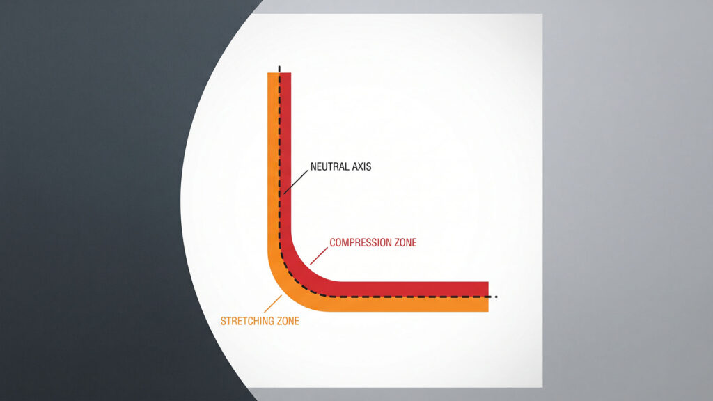
The K-factor is a numerical ratio representing the precise location of the neutral axis within a piece of sheet metal during a bend.
Think of it like a percentage. If your K-factor is 0.50, the neutral axis is sitting perfectly in the dead center of the metal. If your K-factor is 0.40, the line has shifted and sits 40% of the way in from the inside edge.
What Changes Your K-Factor?
The K-factor is not a permanent number. It changes based on the physical reality of your shop.
Material Type, Hardness, and Thickness
Different metals stretch differently. Soft aluminum gives way easily when bent, so its neutral axis shifts closer to the inside edge. Hard stainless steel resists stretching, so its neutral axis stays closer to the middle.
Thickness also matters. Thicker metal forces the neutral axis to shift more than thin metal does.
The Tooling Impact
Your punch and die are critical variables. Let’s look at the data straight from our machines.
Say you take a piece of 11-gauge mild steel and bend it over a standard 1-inch V-die on one of our AMADA press brakes. Your K-factor might sit right at 0.45.
Now, take that same piece of metal and force it into a tight 0.5-inch V-die. You just pinched the bend radius. Because of that tighter tooling, your K-factor drops to 0.42. The metal never changed, but your tools did.

The Hidden Variable: Material Batch Shifts
This variable frequently causes tolerance errors.
Just last year at ShincoFab, we ordered a pallet of 14-gauge 304 Stainless Steel. The first batch came from a mill in Ohio. We tested it and found a perfect K-factor of 0.44.
Two months later, we received a new pallet of 14-gauge 304 stainless from an overseas mill due to supply chain delays. It looked visually identical. But because the microstructure and heat treatment condition of 304 stainless steel can change mechanical properties, the new batch produced a slightly different K-factor of 0.46.
If we had used our old numbers on this new batch, our flanges would have suddenly measured too short. Because we tested it, we avoided a production error.
Your Quick-Reference K-Factor Chart
You should make a habit of testing your metal. But you need a baseline to start those tests.
Starting Numbers for Steel, Aluminum, and Stainless
The ideal K-factor varies by material hardness. Soft aluminum typically ranges from 0.38 to 0.41, while hard stainless steel ranges from 0.43 to 0.46.
Use these typical numbers as your starting point for standard air bending:
| Material Type | Typical K-Factor |
|---|---|
| Aluminum (Soft) | 0.38 to 0.41 |
| Mild Steel / Cold Rolled | 0.42 to 0.46 |
| Stainless Steel (Hard) | 0.43 to 0.46 |
How to Calculate the K-Factor
The Basic K-Factor Formula
The formula is a standard engineering ratio, widely explained in sheet metalworking course notes, and it works as a simple division problem: K = t / T.
- t is the distance from the inside surface of the bend to the neutral axis.
- T is the total thickness of the sheet metal.
Divide the small distance by the total thickness. That is your K-factor.
How K-Factor Connects to Bend Allowance
Why do we need this ratio in the first place? To calculate the Bend Allowance.
Bend Allowance is the calculated length of metal needed to make the curve of the bend itself. You take your flat flange lengths, add the Bend Allowance, and you get the total length of your flat pattern.
The math is a chain reaction. If your K-factor is wrong, your Bend Allowance is wrong. If your Bend Allowance is wrong, your flat pattern is cut to the wrong size.
Using K-Factor in 3D CAD Software
Setting Up SolidWorks and Fusion 360
Adding your K-factor to CAD software takes just a few clicks. In SolidWorks, you manage it through Sheet Metal Properties. In Fusion 360, you define it in the create sheet metal rules workflow.
You punch in the material thickness, your bend radius, and the K-factor. The software instantly spits out a flat pattern.

POV: Stop Trusting Your CAD Software Defaults
Here is the hard truth. You should avoid blindly trusting CAD defaults.
Programs like SolidWorks usually default to a K-factor of 0.5 or 0.33. The computer does not know what press brake you are using. It does not know the exact width of your V-die or how worn your tooling is. Those default numbers are assumptions.
The real K-factor does not live in a computer. It lives on your shop floor.
How to Find Your Exact K-Factor with a Shop Test
The most reliable way to get an accurate flat pattern is to reverse-engineer your K-factor. You have to bend real metal.
The ROI of Testing: The ShincoFab 12-Minute Rule
Many shops skip testing because they think it eats up production time. That is a costly mistake.
We tell every new operator at ShincoFab: It takes about 12 minutes to cut, bend, and measure a test strip. Compare that 12 minutes to a bad production run. A wrong K-factor will easily cost you 4 to 6 hours of welding rework, grinding, and trying to force out-of-tolerance parts together.
Spending 12 minutes up front is one of the best returns on investment your shop will make all day.
Step 1: Cut and Bend a Test Strip
Grab a scrap piece of the actual metal you plan to use. Cut a simple, flat strip. A good size is 4 inches wide by 10 inches long.
Measure the precise thickness with your calipers. Then, take it to the press brake. You must use the same punch and die you will use for the final job. Bend the strip to precisely 90 degrees.

Step 2: Measure and Reverse-Engineer the Formula
Now, measure the length of the two bent legs.
Add those two lengths together. Subtract that total from your starting flat length (10 inches). This gives you your Bend Deduction. To find Bend Allowance, use the formula: Bend Allowance = (2 x Flat Leg Length) – Bend Deduction. For example, if your flat leg lengths are 4.5 inches each and your Bend Deduction is 0.125 inches, your Bend Allowance would be (2 x 4.5) – 0.125, equaling 8.875 inches.
Once you have your Bend Allowance, you plug it into the basic formula to find your K-factor. Now your CAD designer has a proven number to use, not a software guess.
Implementation: How Often Should You Retest?
Do you need to run a test every day? No.
But it is highly recommended to test when a major variable changes. You should run a quick 12-minute test whenever you get a new pallet of metal from a different supplier. You should also test if you change to a wider V-die.
Once you test a specific material and tooling combo, write it down. At ShincoFab, we build a master digital reference sheet so everyone is on the same page.
Troubleshooting Parts Measuring Too Long or Short
Let’s say you did everything correctly. You ran a test. You entered the numbers. But the first production part off the press brake still measures out of tolerance.
Don’t panic. You can fix this right now on the fly.
- If your flange is measuring too long. Your flat pattern gave the bend too much material. Go back to your software. Lower your K-factor by 0.01 and cut a new blank.
- If your flange is measuring too short. Your flat pattern didn’t give the bend enough material. Go back to your software. Raise your K-factor by 0.01.
Make these tiny adjustments one step at a time. Do not make large jumps. Tweak the number, bend a new blank, and measure again until your part is in tolerance.
Bridging the Gap: Who Owns the K-Factor?
This troubleshooting step brings up a common debate in manufacturing. Who actually dictates the K-factor? Is it the design engineer sitting in the office? Or is it the operator standing on the floor?
At ShincoFab, our philosophy is simple: they have to share it.
The engineer controls the digital file. But the operator controls physical reality. The operator on the floor sees firsthand how the metal is behaving inside the V-die today.
If an operator has to tweak the K-factor by 0.02 to make a good part, they should not keep that a secret. They must feed that real-world data back to the engineering team. We use an internal messaging channel specifically for our operators to flag these minor tooling adjustments.
The design team must then update the master CAD file with the floor’s proven numbers.
When you close this communication loop, the magic happens. Engineers stop guessing. Operators stop fighting bad flat patterns. Ultimately, mastering the K-factor is just about replacing assumptions with real data, so you can build parts that fit consistently.
Conclusion
Bending sheet metal doesn’t have to be a guessing game. When you take a few minutes to find your working K-factor, your entire workflow changes.
Your engineers design with confidence. Your operators stop fighting bad parts. Most importantly, your scrap bin stays empty.
Here at ShincoFab, our sheet metal fabrication team relies on these physical tests daily. We know from experience that real-world data consistently outperforms a software default. We don’t guess on our factory floor, and neither should you.
The next time you get a new batch of metal, just remember the basics:
- Avoid blindly trusting your CAD software defaults.
- Run a quick 12-minute bend test.
- Make sure your operators and designers share their numbers.