If you have ever received a batch of parts that refused to bolt together, you know how expensive bad sheet metal tolerances can be.
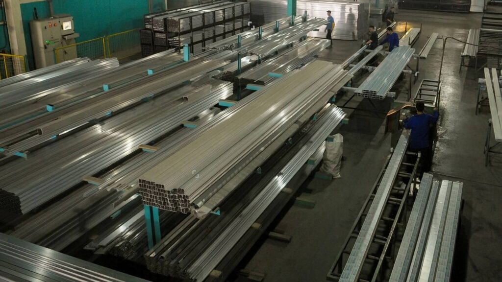
At ShincoFab, we process tons of raw steel and aluminum every month. I have spent years working on the factory floor, standing between our laser cutters and press brakes, fixing broken engineering drawings. I have seen exactly what makes a design cheap to build, and I’ve watched assembly teams literally take hammers to parts that failed on the assembly line.
In this guide, I will show you exactly how to set your tolerances based on what actually works on our shop floor. You will learn the only ISO standard you actually need to use, how to avoid the “powder coat trap,” and a simple design trick to guarantee your parts fit together perfectly every single time.
Stop guessing on your blueprints. Read this, and you will learn how to make your parts easier to manufacture and much cheaper to buy.
What Are Sheet Metal Tolerances?
Nothing in manufacturing is 100% perfect.
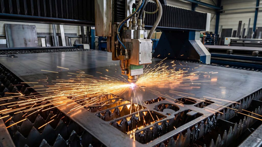
Every time a 10,000-watt laser cuts or a 100-ton press brake bends a piece of metal, there will be a tiny difference from your original drawing. A tolerance is the acceptable amount of dimensional error allowed during the manufacturing process.
The Wiggle Room of Manufacturing
Think of a tolerance as your design’s wiggle room.
You might ask us to cut a piece of steel exactly 10 inches long. In reality, the machine might cut it to 10.01 inches or 9.99 inches.
- If the cut falls inside your wiggle room, the part is good.
- If it falls outside, the part goes in the scrap bin.
Setting the right wiggle room is crucial. It ensures your final parts actually fit together without forcing the manufacturer to work at an impossibly slow pace.
Sheet Metal vs. Machining
I see designers make one huge mistake all the time. They design sheet metal parts exactly like CNC machined parts. You can’t do this.
Machining is a subtractive process that involves carving a shape out of a solid block of material in a highly controlled space. This gives you extreme, microscopic precision.
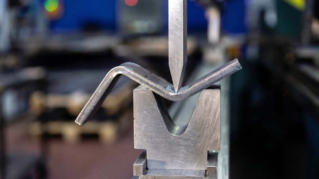
Sheet metal fabrication is an entirely different process that involves cutting flat sheets and smashing them with heavy V-dies to force bends.
When you do this, the metal stretches. It warps. It naturally wants to spring back to its original shape. Because of this stretching and fighting, bent sheet metal requires much more wiggle room than a solid, machined block.
Demanding perfect, machine-like precision on a folded piece of metal makes production messy, slow, and extremely expensive.
Why You Need to Care About Tolerances
If you just guess on your drawing, you will run into two massive problems. It all comes down to your time and your money.
Assembly Nightmares
Imagine opening a box of newly fabricated parts. They look perfect. But when you try to bolt the lid to the base, the holes miss each other by a fraction of an inch.
You can’t force the screws in. You grab a drill to widen the holes, ruining the paint job. Production completely stops.
This is a classic assembly nightmare. It usually happens because a designer forgot that bent metal shifts during production. Smart tolerances prevent this headache. They guarantee your parts slide together easily, right out of the box.
The Cost Factor
Unrealistic tolerances are the fastest way to drain your budget.
When you demand extreme, unnecessary precision, your fabricator has to change how they work. Here is what happens behind the scenes at our factory:
- Machines must run at slower speeds.
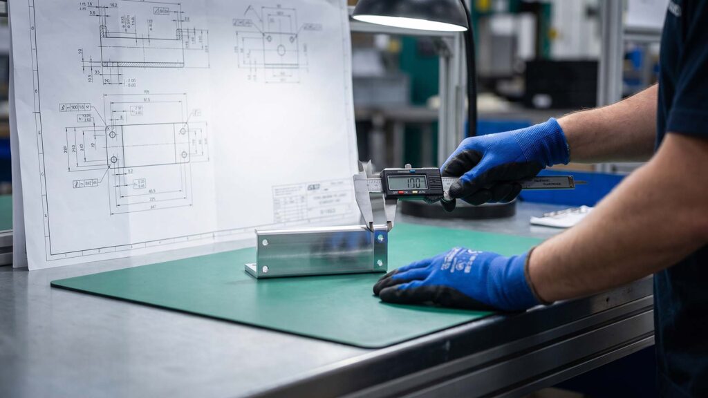
- Workers spend extra time measuring parts by hand using digital calipers.
- Perfectly good parts get thrown in the scrap bin just for being a hair off.
You end up paying for all that extra time and wasted material. Your quote goes up, but the part doesn’t actually work any better.
In fact, a common mistake designers make skyrockets the price almost instantly. It involves just a single, tiny number on a blueprint.
The Cost of a Zero Rule: How Over-Tolerancing Ruins Budgets
The most expensive mistake you can make on a drawing is what I call the Cost of a Zero rule.
If you want a simple bracket made out of 5052 Aluminum, you might write down a tolerance of ±0.1 for the width. Any standard machine can hit that target easily.
But then, you decide to play it extra safe. You add one little zero to your drawing. You change the tolerance from ±0.1 to ±0.01.
That single zero just doubled your price. Why? Because you forced our team into panic mode. To hit that extreme number, they have to jump through three expensive hoops:
- They can’t use standard punches and must buy custom tooling.
- They have to run their machines at a crawl.
- Our Quality Control tech has to stop and manually inspect every single part with expensive gauges.
The truth is, most sheet metal parts never need that level of perfection. A metal box holding a circuit board does not need the same math as a jet engine. Give your parts as much wiggle room as you safely can.
What Are the 3 Main Types of Sheet Metal Tolerances?
Before you can put the right numbers on your drawing, you need to know what you are actually measuring. There are three primary types of sheet metal tolerances: material tolerances, dimensional tolerances, and angular tolerances.
Material Tolerances
Before a laser even touches your part, the raw metal is already slightly off.
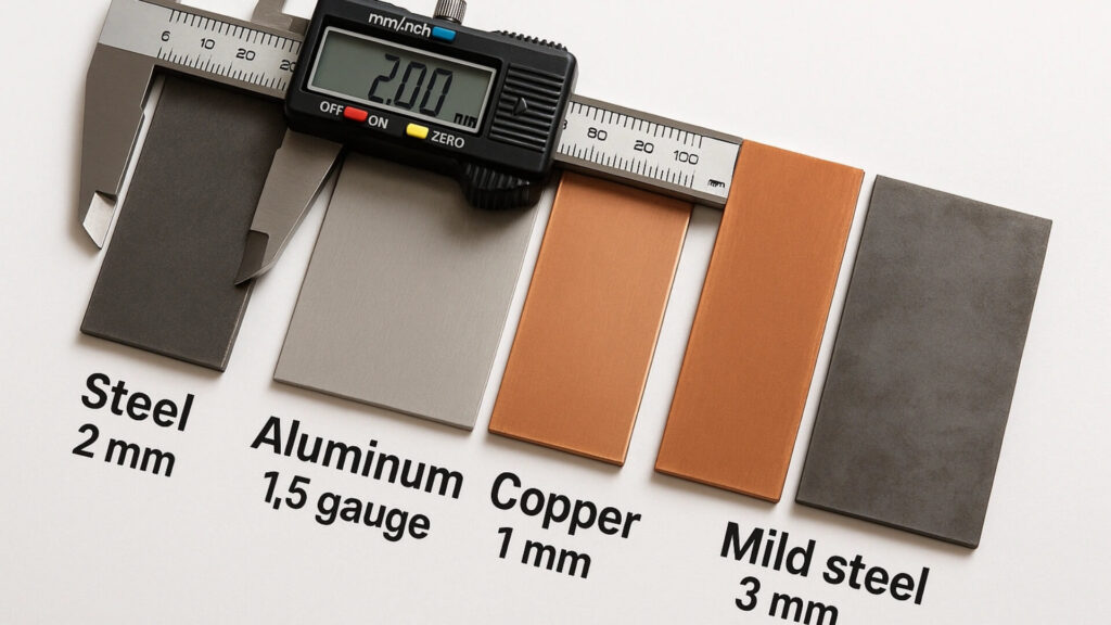
Most people assume an 11-gauge (3mm) steel sheet is exactly 3mm thick. It isn’t. When factories roll out large coils of metal, the thickness naturally changes from batch to batch. We’ve seen single sheets arrive that are noticeably thicker on one edge than the other.
You must plan for this natural material variation before you do anything else.
Dimensional Tolerances
This is the one you will use the most. Dimensional tolerances control the flat size of your features. Specifically, they define the following key measurements:
- The overall length and width of your part.
- The exact diameter of cut holes.
- The distance from an edge to a hole.
If these numbers are too tight, your price goes up. If they are too loose, your mounting bolts won’t fit.
Angular Tolerances
Bending metal is a fight. An angular tolerance controls how close your machine gets to the perfect bend.
If you need a 90-degree corner, the machine might actually hit 89.5 degrees or 90.5 degrees. You have to give the fabricator a degree or two of freedom here. If you don’t, our operators will spend hours manually adjusting the press brake just to hit your exact number.
What is the ISO 2768 Sheet Metal Tolerance Standard?
You do not need to write a custom tolerance for every single line on your drawing. That takes too much time and clutters up your blueprint.
Instead, engineers use an international standard called ISO 2768. Think of it as a universal baseline. You drop one note on your drawing, and it automatically sets the rules for the whole part.
The Medium (m) Class
The ISO standard is broken into different levels of precision. For sheet metal, you only need to care about one: the Medium (m) class.
This is the golden rule for 95% of all commercial parts. It provides the perfect balance of quality and cost.
All you have to do is type “General Tolerances: ISO 2768-m” in the corner of your drawing. This simple note tells our shop to use standard machine settings. You get functional parts quickly, and you avoid paying premium prices.
If you are setting up your drawings and need the hard reference data, here are the standard linear and angular tolerances for the ISO 2768-m class:
ISO 2768-m Linear Tolerances:
| Nominal Length (mm) | Tolerance (mm) |
|---|---|
| 0.5 up to 3 | ± 0.1 |
| Over 3 up to 6 | ± 0.1 |
| Over 6 up to 30 | ± 0.2 |
| Over 30 up to 120 | ± 0.3 |
| Over 120 up to 400 | ± 0.5 |
| Over 400 up to 1000 | ± 0.8 |
ISO 2768-m Angular Tolerances:
| Length of Shorter Leg (mm) | Tolerance |
|---|---|
| Up to 10 | ± 1° |
| Over 10 up to 50 | ± 0°30′ (± 0.5°) |
| Over 50 up to 120 | ± 0°20′ (± 0.33°) |
| Over 120 up to 400 | ± 0°10′ (± 0.16°) |
When to Ignore the Standard
The standard shouldn’t apply to absolutely everything. Ignore it when a specific feature is critical to your assembly.
- Does a hole need to perfectly align with a custom circuit board?
- Does a tab have to slide tightly into a slot?
When a feature really matters, you give it its own specific, tighter tolerance. This is where GD&T (Geometric Dimensioning and Tolerancing) comes into play. Instead of applying tight rules everywhere, you use GD&T callouts—like specifying the true position of those critical mounting holes or the flatness of a mating surface—to control only what matters.
These custom GD&T callouts will always override your general ISO 2768-m block standard. Give the tight numbers and geometric controls only to the features that truly need them.
How Your Fabrication Process Changes the Rules
Your blueprint looks great on a computer screen, but different fabrication machines change the metal in very different ways.
Laser Cutting vs. Punching
When we cut your flat metal, we usually use a laser or a punch press. They do not act the same way. A laser uses extreme heat to slice through the steel, while a punch press relies on brute physical force.
Material pull-down is the physical stretching and deformation that occurs around a hole when a punch press slams a heavy steel tool into the metal. You have to expect these tiny shifts. Heat and physical force will always leave a mark.
Bending and the Springback Effect
Springback is the natural tendency of bent metal to partially unbend itself once the pressure of a press brake is removed.
When a heavy press brake pushes down to fold a piece of metal, the metal fights back. It does not want to stay bent. Every type of metal springs back differently. A piece of 304 Stainless Steel fights back much harder than standard 5052 Aluminum.
A good fabricator will over-bend the metal slightly, expecting it to bounce back to your exact angle. But it is never a perfect science. You must leave room for this natural variation.
Even if your part is cut and bent perfectly, one final step ruins more perfectly sized parts than anything else: the finish.
Don’t Forget the Paint: Finishes Change Everything
You designed the perfect part. The shop cut it flawlessly. The bends are exact. Then, you send it out for paint.
The Powder Coat Trap
Powder coating is a finishing process that involves baking a thick layer of liquid plastic directly onto your metal surfaces.
This added thickness is the “powder coat trap” that catches so many designers. Typically, powder coat adds about 2 to 3 mils (0.05 to 0.08 mm) per surface. We are talking about adding material to every single surface of your part.
If you have a tightly toleranced hole, the paint will shrink its diameter. If you have a metal tab meant to slide into a slot, the paint will make it too fat to fit.
To fix this, you have two options. You must tell us to plug those critical holes before painting, or you must design the holes a little larger from the start.

Why Do Sheet Metal Assemblies Fail?
Tolerance stacking is the compounding accumulation of tiny, individual manufacturing errors across multiple bends or features in a single part. It is the sneakiest reason your assemblies fail.
How Errors Add Up Across Multiple Bends
Your fabricator might follow your tolerances perfectly on every single step, but your parts still won’t fit together because of this stacking effect.
When you build a metal box with a flat lid, the laser places the mounting holes on the flat sheet with perfect accuracy.
But the box itself is folded into a shape. The mounting holes on the box sit on flanges separated by three or four different bends. If each bend is off by just a tiny fraction of a degree, those errors add up. They stack.
By the time the machine makes the final bend, the hole location has shifted. The perfectly flat lid will no longer line up with the bent box. You will be stuck holding a bolt that won’t go into the hole.
You cannot eliminate this bending error completely. But you can use a brilliant design trick to make it totally irrelevant.
The Slot Strategy for Painless Assembly
The Slot Strategy is the design practice of using elongated oval slots instead of standard round holes for mounting hardware.
When you use an elongated slot, you build physical wiggle room directly into the part. Here is exactly how the Slot Strategy beats the stacking problem and saves the day:
- If a bend is slightly off, the hole location naturally shifts.
- Because the hole is an oval, the bolt still finds its way through.
- You guarantee your parts will bolt together on the assembly line without a fight.
It is a simple design hack. It completely erases the headache of stacking tolerances.
Slots are a brilliant way to cheat the system and make assembly easy. But there are a few other common sheet metal features that have strict rules you simply cannot cheat.
Design Cheatsheets: Hems, Curls, and Countersinks
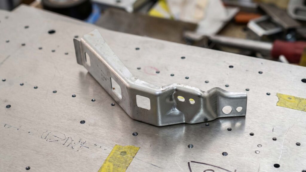
Beyond mounting holes, a few other common sheet metal features come with strict rules. If you ignore these, your parts will warp or break.
Countersink Rules
Countersinks are cone-shaped holes cut into the metal that allow screw heads to sit perfectly flush with the surface.
They look great, but you must keep them away from your bends. If you put a countersink too close to a folded edge, the metal will stretch during the bend. The perfectly round hole will warp into an ugly oval. Your screw will never fit. Always keep countersinks at least three times the material thickness away from any bend.
Hems and Curls
Hems and curls are metal edges that have been folded over onto themselves to hide sharp corners and make parts safe to touch.
But you cannot just fold metal completely flat. If you crush a hem down too tightly, the metal will crack right at the seam. It will look terrible and lose all its strength.
You must give hems and curls a minimum inside radius. A good rule is to make the inside gap equal to the thickness of the metal itself. This keeps the material strong and crack-free.
Conclusion
Every fabrication shop uses different machines. You cannot assume they read your mind. Whether you choose to work with our team at ShincoFab or another manufacturer, ask your fabricator these three simple questions before placing an order:
- “Do you use standard bilateral tolerances?” Make sure you are speaking the same math language. Verify that their default is an equal plus-and-minus variation.
- “What is your default bend deduction?” Every press brake stretches metal slightly differently. Let them give you their specific numbers so your flat pattern calculations actually match their equipment (e.g., matching their K-factor).
- “Do you adjust for powder coating, or should I?” Clarify who is responsible for the paint thickness trap. Figure this out before the parts go into the oven.
When you ask these questions, you open a dialogue. You catch expensive mistakes before anyone cuts a single sheet of metal.
Appendix: Sheet Metal Tolerance Reference Tables
The reference tables below consolidate tolerance data from ISO 2768, JIS B 0408/0410, and industry standards into a single quick-reference guide. Use them alongside your drawing to verify that every dimension is within a range that standard shop equipment can reliably hit.
The appendix PDF covers five areas:
- ISO 2768 General Tolerances — Linear, angular, straightness/flatness, perpendicularity, symmetry, and chamfer tolerances for all four precision classes (f, m, c, v).
- Fabrication Feature Tolerances — Feature-based defaults (sheared edge to hole, formed edge to hole, across bends, overall formed part) in both mm and inches, based on ASM EF-001 industry standards.
- Press Working & Shearing Tolerances — Punching, bending, drawing, and cut-width tolerances by grade (JIS B 0408 / JIS B 0410), including straightness and perpendicularity for sheared plates.
- Material Gauge Thickness Chart — Nominal thickness and bilateral tolerances for gauges 3–30 across five materials: Hot Rolled Steel, Cold Rolled Steel, Galvanized Steel, Stainless Steel, and Aluminum.
- Stainless Steel Sheet Tolerances — Size (length/width), camber, flatness, and standard gage thickness tolerances for flat-rolled stainless sheet (ATI industry standard).