When you are designing for sheet metal, choosing the right material thickness is one of the most important decisions you will make. This isn’t just a minor detail—it effectively sets the foundation for your entire project.
This single variable determines three things: how strong your part is, how much it weighs, and what it costs to produce.
You have to find a careful balance. If you choose a sheet that is too thin, your product might warp or fail under stress. But if you go too thick, you run into different problems. The part becomes unnecessarily heavy to handle, and your production costs will go up much faster than you planned.
This article serves as a comprehensive guide to mastering this critical decision. We will move beyond simple conversion tables to explore the strategic aspects of material selection, supply chain realities, and Design for Manufacturing (DFM) principles. Whether you are scaling a prototype or optimizing a production line, this guide aims to bridge the gap between digital design and physical reality.
What is Sheet Metal Thickness?
Before diving into complex conversion charts, it is essential to categorize what we are actually working with. In the metal fabrication industry, flat rolled products are generally classified into three distinct categories based on their thickness. While the exact cut-off points can vary slightly by international standard, the general consensus divides them as follows:
The Three Categories of Metal Flat Products
Foil
This refers to extremely thin metal sheets, typically measuring less than 0.2mm (0.006 inches) thick. Foil is predominantly used in packaging, electronics shielding, and heat exchange applications. It requires delicate handling as it is prone to tearing and wrinkling.
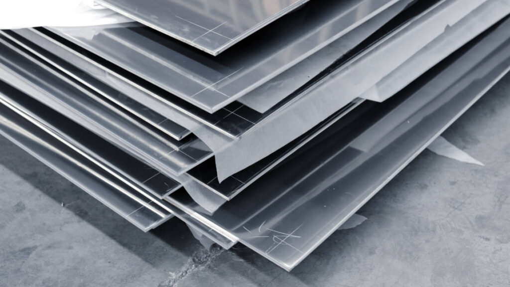
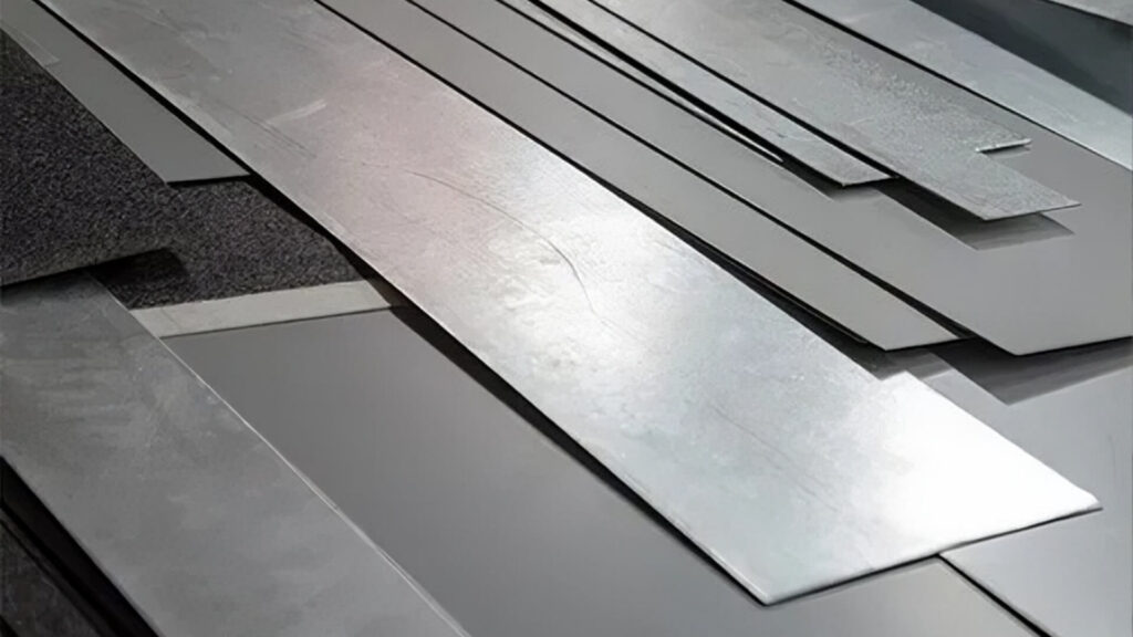
Sheet
This is the core subject of our guide and the most common form used in general fabrication. Sheet metal typically ranges from 0.5mm (0.020 inches) up to 6mm (0.25 inches). It is essentially the “Goldilocks” zone—thinner than structural plate but thicker than foil.
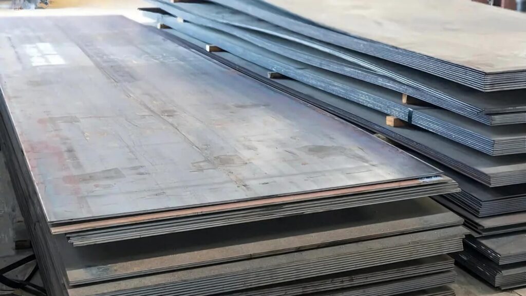
Plate
Metal thicker than 6mm (0.25 inches) is classified as plate. Plate is used for structural applications, such as bridges, heavy machinery bases, and ship hulls.
A Note on Handling
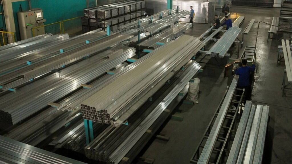
The distinction between Sheet and Plate often dictates the shop floor workflow. Sheet metal (especially in lighter gauges) can often be manipulated by hand or with light-duty vacuum lifters. In contrast, Plate metal is unforgivingly heavy; a single 4×8 sheet of ½-inch steel weighs over 650 lbs, requiring cranes, forklifts, and specialized heavy-duty machinery for bending and cutting.
What is Gauge System
To the uninitiated, the Gauge system is the most confusing aspect of sourcing metal. Understanding its origins helps clarify its logic.
The gauge system originated in the British wire industry before universal measurement standards existed. It was based on the number of times a metal wire had to be drawn through a die to reach a certain diameter. A wire drawn only once (1 gauge) was thick; a wire drawn 30 times (30 gauge) was very thin. This logic was adapted to sheet metal based on weight per square foot. Consequently, the system works on an inverse scale: A higher gauge number equals thinner metal.
Gauge is Not Universal
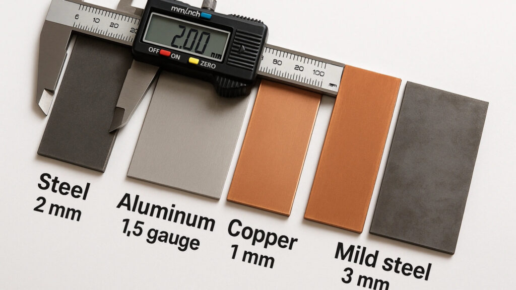
This is the single most critical concept for designers to grasp: Gauge is material-dependent. Because the system relies on weight, and different metals have different densities, the physical thickness of a specific gauge number changes depending on the material.
For example A 16-gauge sheet of Standard Steel is approximately 0.0598 inches (1.52mm). However, a 16-gauge sheet of Aluminum is approximately 0.0508 inches (1.29mm).
If you design a part assuming 16 gauge is a universal thickness, switching materials from steel to aluminum without adjusting your CAD model could result in parts that do not fit, possess insufficient strength, or have incorrect bend deductions.
Measurement Units & Best Practices
Today, the industry faces a conflict between legacy terminology (Gauge/GA) and precision engineering units (Inches or Millimeters). While engineers and purchasing agents often speak in “gauges,” manufacturing machines (lasers) and CAD software operate in exact decimals.
To avoid ambiguity and costly manufacturing errors, always specify the actual thickness in millimeters (mm) or decimal inches on your drawings and purchase orders. Use the gauge number only as a reference, not the primary specification. (e.g., “1.5mm – 16GA CR Steel”).
Material-Specific Gauge Patterns
Since the gauge system is derived from weight, and every metal has a unique density, relying on a single “master chart” is a recipe for disaster. Different material families follow different gauge standards. To select materials accurately, you must understand the specific trends and manufacturing distinctions for each metal type.
Carbon Steel (Mild Steel)
Carbon steel follows the Manufacturer’s Standard Gauge (MSG) which typically aligns with standards set by ASTM International. However, within this category, thickness availability is heavily influenced by the manufacturing method: Hot Rolled vs. Cold Rolled.
- Hot Rolled Steel (Thicker): Produced at high temperatures, this steel typically has a scaly, rough finish. It is generally available in thicker gauges (typically 7 Gauge to 14 Gauge) and plate sizes. It is the go-to for structural components where surface finish is secondary to strength and cost.
- Cold Rolled Steel (Thinner): After hot rolling, this steel undergoes further processing at room temperature to achieve precise dimensions and a smooth, oily finish. It is typically found in thinner gauges (typically 16 Gauge to 28 Gauge). Because of its precision, it is the standard for appliances, automotive body parts, and enclosures.
Stainless Steel
Stainless steel generally follows the U.S. Standard Gauge, not MSG.
Because Stainless Steel is slightly denser than Carbon Steel (due to the chromium and nickel content), a “pound of stainless” yields a slightly smaller surface area or thickness than a pound of mild steel. For the same gauge number, Stainless Steel is often nominally thinner than Carbon Steel.
Galvanized Steel
Galvanized steel introduces a unique variable: the protective zinc layer. Unlike plain steel, the gauge thickness for Galvanized sheet typically refers to the coated thickness, not the base metal thickness.
A 16-Gauge Galvanized sheet measures roughly the same total thickness as a 16-Gauge Standard Steel sheet. However, because that measurement includes the layer of bonded zinc, the actual steel core is thinner than that of an uncoated sheet. If you strip the zinc manufacturing layer away, the structural steel underneath is slightly reduced.
Non-Ferrous Metals
The rules change entirely when moving away from iron-based metals.
Aluminum
While an aluminum gauge chart (based on the Brown & Sharpe standard) exists, the modern industry largely ignores it. Professional fabricators and suppliers almost exclusively specify aluminum by decimal thickness (Inches or Millimeters). You will rarely hear a shop ask for “10-gauge aluminum”; they will ask for “0.100 aluminum” or “0.125 (1/8 inch) aluminum.” Using gauge numbers for aluminum is considered outdated and can lead to significant confusion.
Copper and Brass
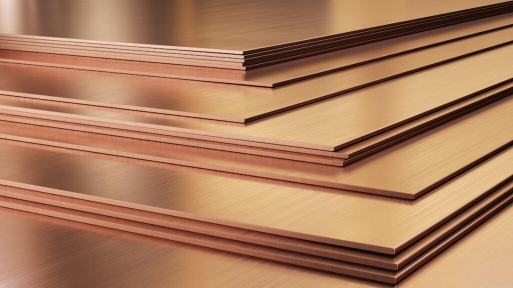
These materials typically use the Brown & Sharpe (B&S) or American Wire Gauge (AWG) systems. These standards are completely different from the steel standards. For example, 16-gauge steel is ~0.060″, but 16-gauge copper (B&S) is ~0.050″. The difference is roughly 20%, which is a massive margin of error in manufacturing.
Standard Sheet Metal Gauge Charts
To help you navigate the differences between materials, we have compiled the standard gauge conversion charts below.
The values below are nominal. As discussed earlier, actual mill tolerances usually result in material being slightly thinner than the nominal value. Always confirm specific tolerance requirements with ShincoFab before production.
1. Standard Carbon Steel (MSG)
The most common manufacturing standard. Note that 16 GA is the industry “workhorse” for enclosures.
| Gauge | Thickness (in) | Thickness (mm) | Common Application |
|---|---|---|---|
| 7 | 0.179 | 4.55 | Heavy-duty structural hinges, truck chassis components |
| 8 | 0.164 | 4.18 | Heavy-duty brackets, outdoor infrastructure mounts |
| 10 | 0.135 | 3.42 | Industrial stair treads, heavy equipment enclosures |
| 11 | 0.120 | 3.04 | Structural panels, automotive chassis parts |
| 12 | 0.105 | 2.66 | Robust electrical cabinets, door frames |
| 14 | 0.075 | 1.90 | Standard industrial enclosures (NEMA boxes), server racks |
| 16 | 0.060 | 1.52 | Industry Standard for PC cases, light fixtures, cabinets |
| 18 | 0.048 | 1.21 | Light-duty covers, appliance panels, drip pans |
| 20 | 0.036 | 0.91 | Interior decorative panels, sign backings |
| 22 | 0.030 | 0.76 | HVAC ducts, light-duty flashing |
| 24 | 0.024 | 0.61 | Kitchen range hoods, air ducts |
| 26 | 0.018 | 0.45 | Corrugated roofing, economical rigid packaging |
| 28 | 0.015 | 0.38 | Thin flashing, tags, non-structural covers |
2. Galvanized Steel
Thickness usually includes the zinc coating. essential for outdoor/humid environments.
| Gauge | Thickness (in) | Thickness (mm) | Common Application |
|---|---|---|---|
| 10 | 0.138 | 3.51 | Outdoor structural supports, solar racking |
| 12 | 0.108 | 2.75 | Garage door hardware, electrical boxes |
| 14 | 0.079 | 1.99 | Outdoor HVAC units, fence brackets |
| 16 | 0.064 | 1.61 | Standard for ductwork, warehouse shelving |
| 18 | 0.052 | 1.31 | Gutters, downspouts, automotive body panels |
| 20 | 0.040 | 1.01 | Flexible ductwork, metal roofing (standing seam) |
| 22 | 0.034 | 0.85 | Siding, flashing, corner beads |
| 24 | 0.028 | 0.70 | Spiral ducts, lightweight housings |
| 26 | 0.022 | 0.55 | Corrugated siding, ventilation pipes |
| 28 | 0.019 | 0.48 | General purpose flashing, trim |
3. Stainless Steel
Slightly thinner than carbon steel at the same gauge. Used for hygiene and corrosion resistance.
| Gauge | Thickness (in) | Thickness (mm) | Common Application |
|---|---|---|---|
| 7 | 0.188 | 4.76 | Heavy Chemical tanks, structural flanges |
| 8 | 0.172 | 4.37 | Industrial vat walls, architectural supports |
| 10 | 0.141 | 3.57 | Commercial kitchen counters, medical equipment bases |
| 11 | 0.125 | 3.18 | Food processing chutes, elevator panels |
| 12 | 0.109 | 2.78 | Heavy-duty restaurant tables, kick plates |
| 14 | 0.078 | 1.98 | Standard for excessive-use surfaces, laboratory tables |
| 16 | 0.063 | 1.59 | Kitchen sinks, countertops, cleanroom enclosures |
| 18 | 0.050 | 1.27 | Appliance skins (Fridges), backsplashes |
| 20 | 0.038 | 0.95 | Exhaust hoods, decorative trim |
| 22 | 0.031 | 0.79 | Light appliance trim, cladding |
| 24 | 0.025 | 0.64 | Utensils, intricate stamped parts |
| 26 | 0.019 | 0.48 | Chimney liners, decorative inlays |
4. Aluminum Sheet
Ideally specified by decimal inch/mm, but gauges refer to B&S Standard.
| Gauge | Thickness (in) | Thickness (mm) | Common Application |
|---|---|---|---|
| 8 | 0.129 | 3.26 | Heavy-duty road signs, structural aircraft parts |
| 10 | 0.102 | 2.59 | Truck bodies, boat hulls |
| 12 | 0.081 | 2.05 | High-strength manufacturing panels |
| 14 | 0.064 | 1.63 | Standard for street signs, electronics chassis |
| 16 | 0.051 | 1.29 | Aircraft skins, fuel tanks |
| 18 | 0.040 | 1.02 | Automotive panels, lighting reflectors |
| 20 | 0.032 | 0.81 | Consumer electronics casings (Laptops) |
| 22 | 0.025 | 0.64 | Heat shields, fins |
| 24 | 0.020 | 0.51 | Nameplates, decorative trim |
5. Copper & Brass Sheet
Used primarily for electrical conductivity or decoration. (B&S Standard)
| Gauge | Thickness (in) | Thickness (mm) | Common Application |
|---|---|---|---|
| 8 | 0.129 | 3.26 | Busbars, heavy electrical distribution |
| 10 | 0.102 | 2.59 | Architectural roofing, sculpture bases |
| 12 | 0.081 | 2.05 | Grounding plates, thick washers |
| 16 | 0.051 | 1.29 | Range hoods, sinks, countertops |
| 18 | 0.040 | 1.02 | Decorative wall cladding, jewelry foundations |
| 20 | 0.032 | 0.81 | Rain gutters, electrical contacts |
| 22 | 0.025 | 0.64 | RF shielding, flashing, crafts |
| 24 | 0.020 | 0.51 | Embossing, shims, gaskets |
Key Factors for Selecting the Right Thickness
Selecting the correct gauge is not just about picking a number from a chart; it is an engineering decision that balances performance, cost, and manufacturability. When defining the specifications for your project, consider these four critical pillars.
Structural Requirements (Load & Strength)
The most obvious function of thickness is providing physical strength, but the type of load dictates the necessary gauge.
Static vs. Dynamic Loads
For static loads (e.g., a shelf holding a computer), the primary concern is preventing deflection or sagging. However, for dynamic loads (e.g., a vibrating motor mount or a moving vehicle part), stiffness becomes critical to prevent fatigue failure.
The Cube Rule of Stiffness
Engineers should remember that stiffness follows a cubic relationship with thickness. Doubling the thickness of a sheet makes it eight times stiffer. Therefore, a small increase in gauge (e.g., moving from 18GA to 16GA) can result in a massive jump in rigidity.
The Trade-off
While thicker is stronger, it is also heavier and more expensive. The goal is to find the minimum thickness that safely meets your load requirements to keep costs and weight efficient.
Manufacturing Processes (The Formability Factor)
A common mistake is selecting a thickness that looks good in CAD but is a nightmare on the shop floor. The gauge you choose dictates which manufacturing methods are viable.
Bending and Forming
- Minimum Bend Radius: Every metal thickness has a minimum radius it can be bent to before it cracks. Thicker metals require larger internal radii. If your design requires a sharp, crisp corner, you may be forced to use a thinner gauge to achieve it without structural failure.
- Springback: Thicker metals store more elastic energy during bending. This causes “springback,” where the metal tries to return to its original shape, requiring more complex tooling adjustments and force to achieve precise angles.
Welding Constraints
- Thin Material Risks: Welding metals thinner than 18 Gauge (~1.2mm) requires high skill or specialized equipment (like Pulse TIG) to avoid “burn-through,” where the heat melts a hole straight through the sheet.
- Thick Material Costs: Conversely, welding heavy gauges often requires beveling edges (chamfering) and multiple weld passes to ensure penetration, significantly increasing labor time and heat distortion risks.
Cutting Limitations
Laser cutters and punch presses have power limits. As thickness increases, cutting speed drops drastically. Cutting 1/4″ plate is significantly slower—and therefore more expensive per part—than cutting 14-gauge sheet.
Weight Management
Weight is a silent cost driver that extends beyond the raw material price.
Performance Weight
In industries like automotive, aerospace, or even portable consumer electronics, every gram counts. Selecting a 20-gauge aluminum sheet over a 16-gauge steel sheet can reduce assembly weight by over 60%, directly impacting fuel efficiency or portability.
Logistics Weight
Never overlook shipping and handling. A product designed with 10-gauge steel might be too heavy for a single operator to lift, requiring two-person teams or forklifts for installation. This adds hidden labor costs and increases freight shipping rates.
Environment & Durability
Where will the part live? The operating environment should influence your thickness choice just as much as structural loads.
Corrosion Allowance
In outdoor or marine environments, metal will inevitably oxidize over time. Designers often choose a slightly thicker gauge than structurally necessary to act as a sacrificial layer. If a 20-gauge sheet rusts 0.2mm, it might lose structural integrity; if a 12-gauge sheet rusts 0.2mm, it remains functional.
Indoor vs. Outdoor
Indoor enclosures (server racks, electrical boxes) are protected from the elements and can utilize thinner, lighter gauges (often 16GA to 20GA). Outdoor infrastructure (NEMA enclosures, roofing) requires heavier gauges (10GA to 14GA) to withstand wind loads, hail impact, and thermal cycling.
Real-World Sourcing & Supply Chain Strategy
Designing the perfect part is only half the battle; sourcing the material to build it is the other. A common friction point between engineering and purchasing departments stems from specifying materials that are technically possible but logistically impractical. Understanding the supply chain can significantly reduce costs and lead times.
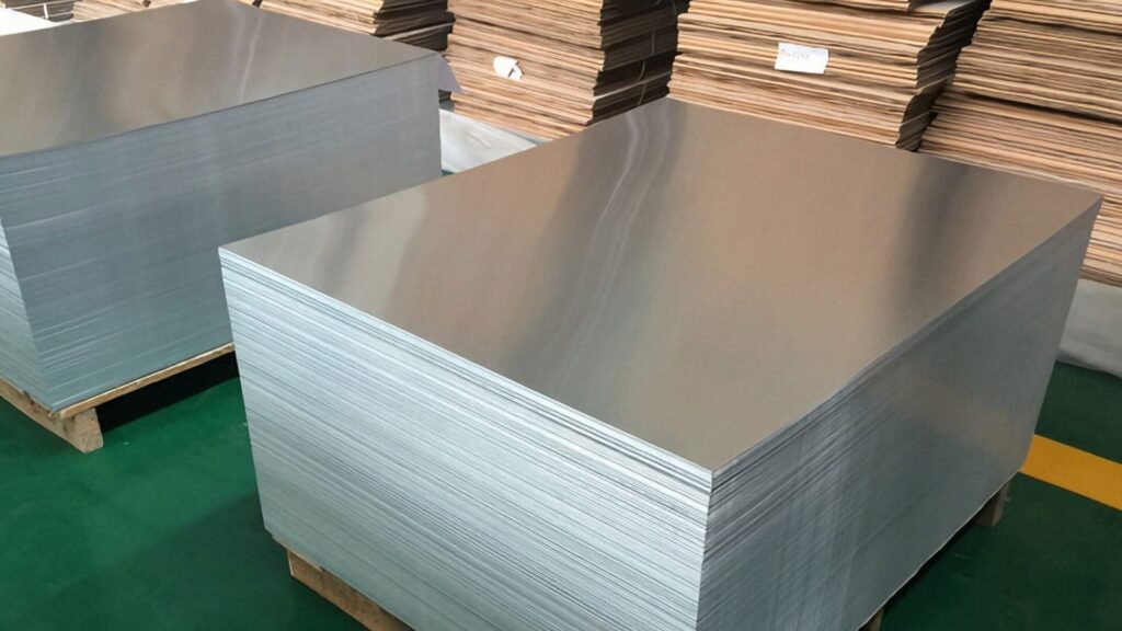
Standard Stock Sizes & Nesting Efficiency
Sheet metal is not available in infinite dimensions. It is typically supplied in standard sheet sizes, much like plywood or drywall. In North America, the most common stock sizes are 4′ x 8′ (48″ x 96″), 4′ x 10′ (48″ x 120″), and 5′ x 10′ (60″ x 120″). In metric, this translates roughly to 1.2m x 2.4m and 1.5m x 3.0m.
The Nesting Strategy
“Nesting” refers to how many parts a fabricator can fit onto a single sheet.
The Trap: Designing a part that is 47.5″ wide sounds fine for a 48″ sheet. However, laser cutters require a border (skeleton) for stability—usually 0.5″ to 1″. A 47.5″ part will not fit on a 48″ sheet, forcing the shop to buy a larger, more expensive 60″ sheet or accept massive scrap rates. Always design with the raw sheet size minus the kerf and clamp margin in mind to maximize yield and lower unit price.
Availability vs. Lead Time
Just because a thickness exists on a gauge chart does not mean it is sitting on a shelf. Most fabrication shops keep high volumes of 10, 11, 12, 14, 16, 18, 20, and 24 gauge steel in stock. These are industry workhorses. Gauges like 13, 15, 17, or 19 are rarely stocked.
If your design specifies 17-gauge steel, the fabricator has two choices: wait weeks for a mill order (likely with a high minimum purchase weight) or substitute it with 16-gauge (thicker/heavier). Unless your application has highly specific weight/strength constraints that absolutely rule out standard options, always round your design to the nearest even-numbered gauge. It produces a cheaper, faster product.
Coil to Sheet Processing
It is important to remember that most sheet metal originates as massive, tightly wound coils weighing thousands of pounds. To produce flat stock, these coils are unrolled and passed through leveling machines in a process known as “cut-to-length.” However, metal possesses “material memory”—a physical tendency to try to return to the curvature of the coil. While modern leveling technology is advanced, residual stresses often remain, particularly in thinner materials (typically 24GA to 18GA).
This internal tension frequently manifests as “oil canning“, a defect where large, unsupported flat areas exhibit a wavy, buckled appearance. To avoid this aesthetic issue in high-visibility applications—such as architectural facades or appliance doors—engineers should be cautious when specifying thin gauges for large flat panels. Instead, consider opting for thicker material (16GA+) or incorporating stiffening ribs into the design to counteract the natural stress and maintain a truly flat surface.
Practical Tools & Measurement
Whether you are verifying incoming inventory or reverse-engineering an existing part, knowing how to measure thickness accurately is essential. Different scenarios require different tools, and mishandling materials during measurement can lead to injury.
The Toolbox Essentials
The Sheet Metal Gauge Tool (The Wheel)
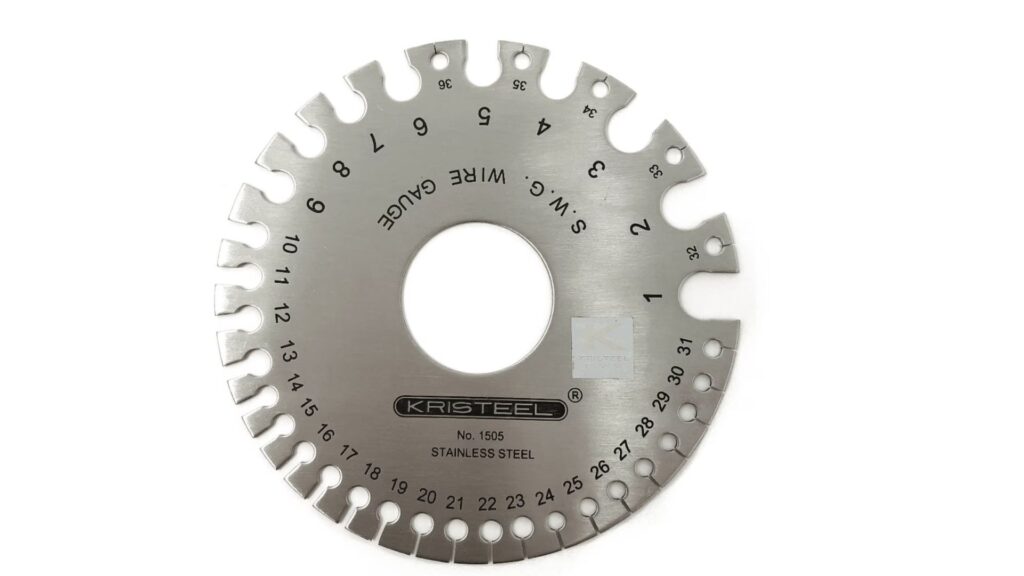
This circular steel tool is the industry standard for quick ID. It features pre-cut slots corresponding to different gauge numbers.
How to use it: Slide the metal into the slot (the gap), not the hole at the bottom of the slot. The correct gauge is the smallest slot the metal fits into comfortably without being forced.
Crucial Note: There are different wheels for Ferrous (Steel/Iron) and Non-Ferrous (Aluminum/Copper) metals. Using a steel gauge wheel to measure aluminum will result in incorrect readings because of the differing standards.
Calipers and Micrometers
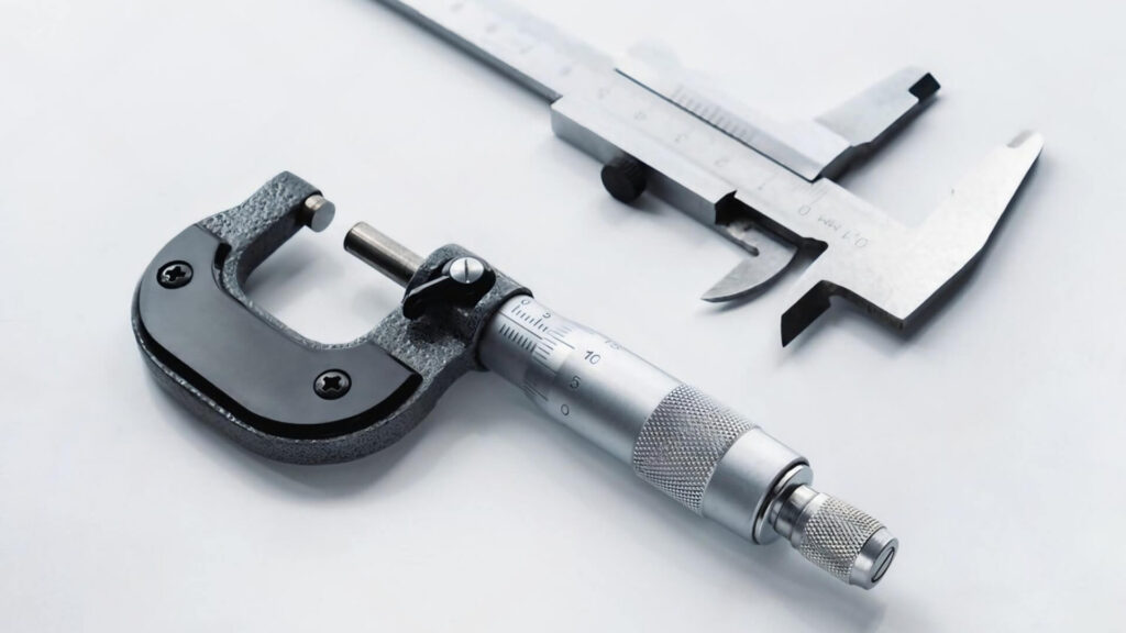
For engineering verification, the gauge wheel is too imprecise. Digital calipers or micrometers are necessary to read the actual decimal thickness (e.g., 0.057″). This is the only way to determine if a sheet is at the high or low end of the mill tolerance range, which is critical for precision press-fit applications.
Advanced Measurement: Ultrasonic Thickness Testers
What happens if you need to measure the thickness of a closed box, a tank, or a pipe where you cannot access the other side to use calipers? You can try ultrasonic thickness testers. These handheld devices use high-frequency sound waves to measure how long it takes for a pulse to travel through the metal and reflect back.
They are invaluable for Quality Assurance (QA) on finished assemblies or for checking corrosion/wall thinning on installed maintenance equipment without destroying the part.
The Hazard Spectrum
Sheet metal changes its personality as it changes thickness. The safety protocols must adapt accordingly.
Thin Sheets (The Razor Risk)
Gauges typically 18GA and thinner retain an incredibly sharp sheared edge. They are flexible and can “whip” when moved. The primary risk here is laceration. Deep cuts can occur instantly from sliding a bare hand along an edge. Always wear cut-resistant gloves (Kevlar/Dyneema) when handling thin stock.
Thick Plates (The Crush Hazard)
As material moves into the Plate category (1/4″ and up), the risk shifts from cuts to crushing. A sheet that looks manageable may weigh hundreds of pounds. Manual lifting can cause severe back injury, and dropping a plate can shatter bones. Heavy plate handling requires steel-toed boots, careful planning of “pinch points,” and often mechanical assistance like magnets or vacuum lifts.
Conclusion
Mastering sheet metal thickness is more than just reading a gauge chart; it determines the critical balance between your product’s structural integrity, weight, and manufacturing cost. Navigating the complexities of the gauge system, material-specific standards, and supply chain availability is essential to bridging the gap between a digital design and a successful physical product. A well-chosen thickness not only ensures performance but also streamlines production and reduces unnecessary waste.
However, you don’t have to navigate these engineering trade-offs alone. At ShincoFab, we help clients worldwide translate complex requirements into precision components. Whether you need guidance on optimizing tolerances for global sourcing or managing the transition from prototype to mass production, our expert team is ready to bring your designs to life. Contact ShincoFab today to ensure your manufacturing strategy is as precise as your engineering.