Custom Heat Sink
Precision Aluminum and Copper solutions engineered to meet your thermal budget ($/W) and dimensional constraints. From rapid prototyping to volume production.
When Standard Heat Sinks Bottleneck Your Thermal Performance
Generic extruded profiles obey the laws of mass production, not the laws of your specific thermal dynamics. Standard fin ratios are simply insufficient for modern high-power density applications including EV inverters (IGBTs), Hyperscale AI Computing, and High-Brightness LEDs.
ShincoFab move beyond the limitations of catalog parts. Our custom manufacturing process allows for higher aspect ratios (up to 50:1), optimized fin density, and complex geometries designed to minimize thermal resistance (θsa) within your strict spatial envelope.
Critical Base Flatness
We control base flatness to 0.002mm/mm. Why does this matter? Because a flatter base reduces the bond line thickness of your Thermal Interface Material (TIM). Minimizing TIM thickness is the fastest way to drop junction temperature (ΔTj), ensuring maximum heat transfer from component to heat sink.
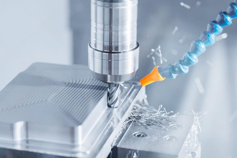
Precision CNC Machining
For mounting features and complex interfaces, we hold tolerances to +/- 0.01mm. This ensures perfect mating with chips, heat spreaders, or liquid cold plates, eliminating air gaps that kill thermal performance.
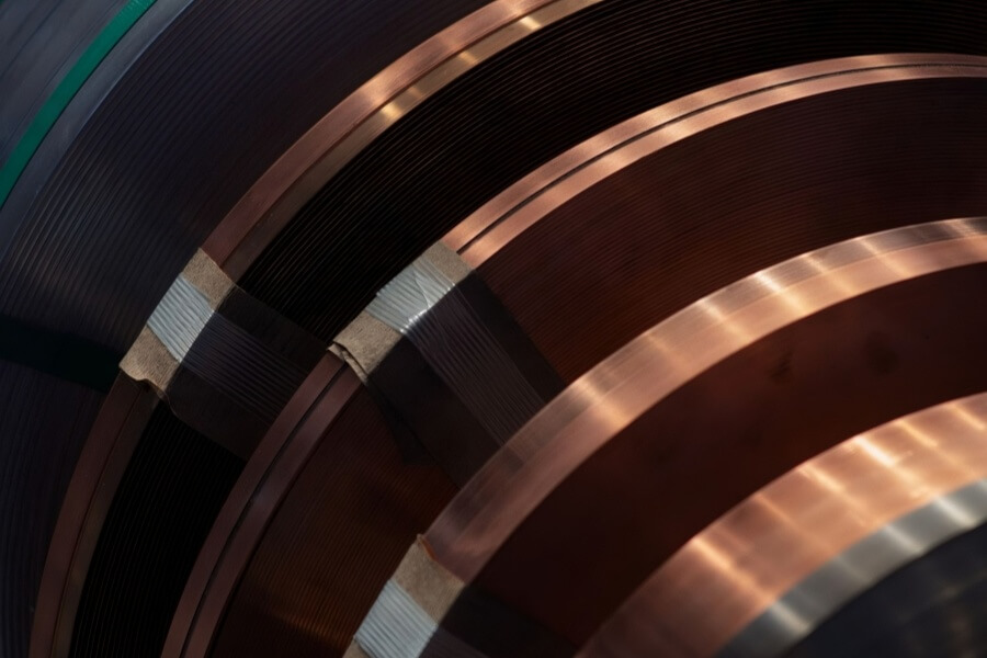
Certified Material Conductivity
We don’t guess with alloys. We use certified Al 6063-T5 (Thermal Conductivity >200 W/mK) for optimal extrusion performance, and High-Purity C11000 Copper (>390 W/mK) for maximum heat spreading. Mill test reports (MTR) are available upon request.
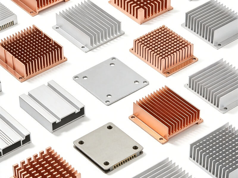
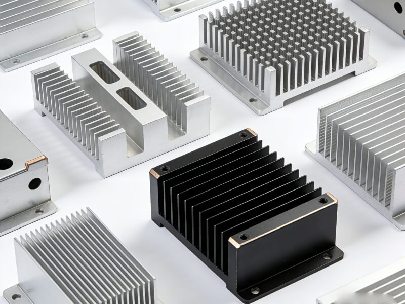
Capabilities Engineered for Thermal Density and Volume
A universal heat sink does not exist. There is only the optimal design engineered for your specific ΔT, available airflow, and target unit cost. ShincoFab offer the full spectrum of fabrication technologies to balance your thermal budget with your production budget.
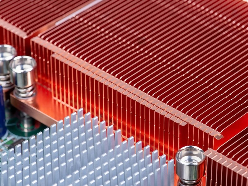
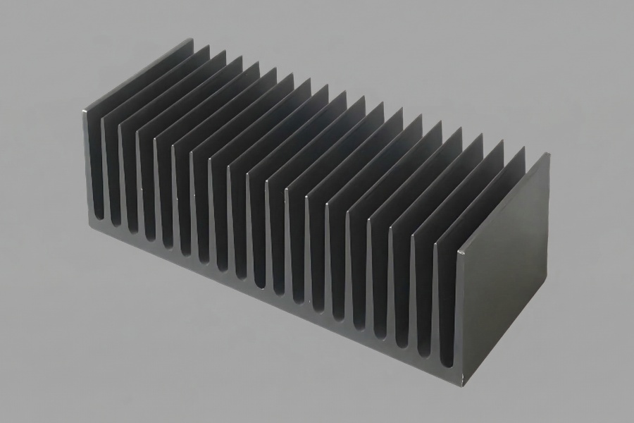
Skived Fins for High-Density Applications
Zero Interface Thermal Resistance for High-Heat Loads.
Unlike bonded fins, skiving shaves fins directly from a solid block of aluminum or copper. This eliminates the thermal barrier of bonding agents or solder, offering the purest thermal path from base to fin.
- The Eng. Advantage: Achieves aspect ratios up to 50:1 with fin thickness as low as 0.25mm. Delivers maximum surface area in restricted spaces.
- Best For: Liquid cooling cold plates, 1U/2U server chassis, and high-performance IGBT cooling.
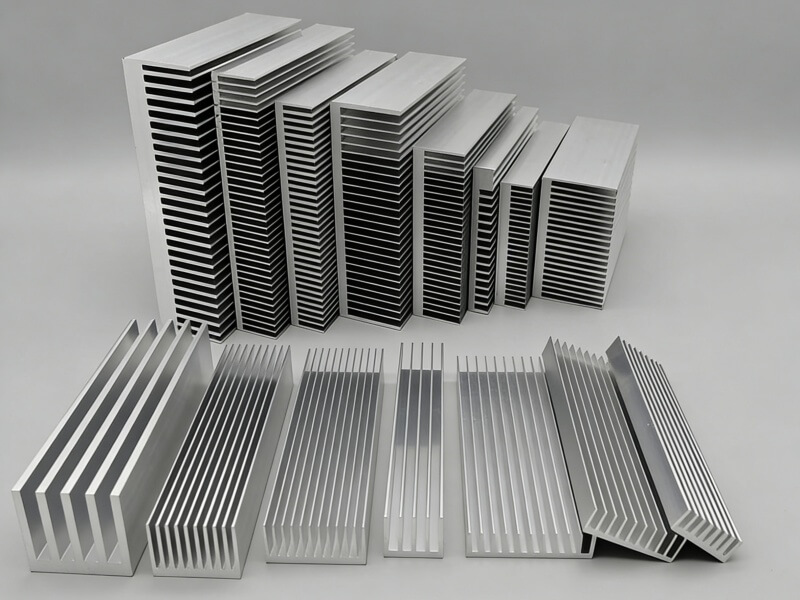
Custom Aluminum Extrusion for High-Volume Efficiency
The Economic Workhorse for Moderate Thermal Loads.
For linear profiles where unit cost is the primary driver, extrusion remains unbeatable. We design and cut custom dies to optimize airflow characteristics within standard manufacturing constraints.
- The Eng. Advantage: Lowest Cost Per Unit (CPU) at scale. We support complex cross-sections and secondary CNC machining for mounting features.
- Best For: Industrial power supplies, LED lighting fixtures, and structural electronic enclosures.
Cold Forging and Die Casting for Complex 3D Geometries
Structural Integrity Meets Thermal Conductivity.
When you need omnidirectional airflow (Pin Fins) or housing integration.
- Cold Forging (The Thermal Choice): High-pressure forming at room temperature increases material density, resulting in higher thermal conductivity than die casting. Ideal for pin-fin arrays that maximize natural convection.
- Die Casting (The Structural Choice): Best for complex net-shapes, covers, and housings where the heat sink doubles as a structural component.
- Best For: Automotive headlamps (Casting), LED downlights (Forging).


Heat Pipes and Vapor Chambers for Extreme Heat Flux
Eliminating Localized Hot Spots with Two-Phase Cooling
When the heat source density (W/cm²) exceeds the spreading capability of solid metal, we integrate two-phase devices.
- The Eng. Advantage: Effective thermal conductivity >5,000 W/mK. Rapidly spreads heat from a concentrated die source across the full fin area of the heat sink, eliminating local hot spots.
- Best For: High-TDP CPUs/GPUs, telecommunications base stations, and compact ASICs.
We Verify the Physics Before You Commit to Tooling Costs
The most expensive way to test a heat sink is to build it, install it, and watch the system overheat. We prevent that. We act as an extension of your thermal engineering team, validating your concept digitally and physically before volume production begins.

CFD Simulation
Don’t Guess Airflow. Visualize It.
Using industry-standard Ansys Icepak and SolidWorks Flow Simulation, we analyze your 3D model under real-world conditions.
- The Output: We identify high-pressure drop zones (ΔP), airflow bypass issues, and predict junction temperatures (Tj) with high accuracy.
- The Value: We catch thermal bottlenecks before metal is cut, saving you weeks of design iteration loops.

DFM Review
Design for Manufacture = Design for Profit.
Our engineers review your CAD files not just for feasibility, but for cost-efficiency.
- The Output: We suggest specific modifications—such as relaxing non-critical tolerances, adjusting fin spacing for tool longevity, or adding draft angles for casting—without compromising thermal performance.
- The Value: Often reduces unit cost by 15-20% and simplifies the transition from prototype to mass production.

Rapid Prototyping in 3-5 Days
Test with Real Materials, Not Plastic.
A 3D-printed SLA model can check fit, but it can’t check thermals.
- The Output: We deliver functional prototypes CNC machined directly from solid blocks of Al 6063 or Cu 1100.
- The Value: You get physical validation of thermal performance and mechanical fit within one week. No tooling investment required for this stage.
Technical Specifications
We strictly adhere to ASTM and ISO material standards. Below are the baseline specifications for our most common heat sink alloys and surface treatments. Custom alloys (e.g., Al 6005, Cu 1020) available upon request.
Standard Engineering Specifications: Materials & Finishes
We strictly adhere to ASTM and ISO material standards. Below are the baseline specifications for our most common heat sink alloys and surface treatments. Custom alloys (e.g., Al 6005, Cu 1020) available upon request.
| Alloy Grade | Thermal Conductivity (k) | Key Engineering Characteristic | Best Application |
|---|---|---|---|
| Al 6063-T5 | ~201 W/m·K | The Extrusion Standard. Excellent surface finish quality and anodizing response. | High-volume extruded profiles; general electronics cooling. |
| Al 6061-T6 | ~167 W/m·K | High Structural Strength. Lower conductivity than 6063, but significantly higher yield strength. | Machined structural components; chassis integrated heat sinks. |
| Cu C11000 | ~390 W/m·K | Electrolytic Tough Pitch (ETP). 99.9% pure copper for maximum heat transfer. | High-flux IGBTs; high-performance skived fins; heat spreaders. |
Surface Treatments: Balancing Emissivity & Conductivity
Black Anodizing (Type II / Type III)
- Physics: Increases surface emissivity (ϵ) from ~0.05 (bare Al) to >0.8, significantly improving radiative heat dissipation in natural convection.
- Electrical: Creates a non-conductive ceramic layer. High dielectric strength.
- Durability: Type III (Hard Coat) provides extreme abrasion resistance fitting for industrial environments.

Electroless Nickel Plating
- Primary Utility: Critical for Copper heat sinks to prevent oxidation (tarnish) without effectively reducing thermal conductivity.
- Assembly: Enables solderability. Essential if you plan to solder heat pipes or vapor chambers directly to the base.

Chromate Conversion (Alodine / Clear Iridite)
- Primary Utility: Provides corrosion protection while maintaining electrical conductivity.
- Best For: EMI/RFI shielding applications where the heat sink must be electrically grounded to the chassis.
Quality Control & Inspection
In high-flux thermal management, a 0.05mm deviation in flatness is not a “tolerance”—it is a failure. We operate under strict ISO 9001:2015 protocols to ensure that the part you receive matches the PDF you approved.
Material Traceability
No Mystery Metal.
We guarantee the chemical integrity of your heat sinks.
- The Standard: Every shipment includes comprehensive Mill Test Reports (MTR) referencing ASTM B221 (Aluminum) or ASTM B152 (Copper).
- The Proof: You receive documentation verifying chemical composition and mechanical properties. We ensure your “6063-T5” is genuine, not scrap-based remelt.

Dimensional Metrology
GD&T Verification for Critical Fits.
We don’t rely on calipers for complex geometries.
- The Equipment: Using high-precision CMM (Coordinate Measuring Machines), we map critical-to-function (CTF) features.
- The Output: Automated inspection reports verify hole positions, true position, and most importantly, base flatness/coplanarity to ensure optimal TIM interface.
100% Functional Testing
For Liquid Cold Plates & Heat Pipes.
Statistical sampling (AQL) is acceptable for fins, but unacceptable for liquid loops.
- The Protocol: 100% Helium Leak Testing for all liquid cold plates and vapor chambers to detect microscopic leaks.
- Thermal Auditing: Random lot sampling for thermal performance (ΔT vs Q) to validate heat pipe efficiency before final packaging.
Have a Thermal Engineer Review Your CAD Before Committing to Tooling Costs
Don't guess on fin density or material selection. Upload your 3D models (STEP/IGES) for a complimentary Design for Manufacturing (DFM) review. We will evaluate your spatial constraints, identify potential thermal bottlenecks, and quote the most cost-effective fabrication method within 24 hours.
Frequently Asked Questions
Clear answers regarding file security, standard lead times, and manufacturing feasibility. Read this before uploading your CAD.
What are the dimensional limits for your Skived Fin process?
We push the limits of aspect ratio. While standard skiving stops at 25:1, our precision machinery achieves ratios up to 50:1. We can produce fins as thin as 0.2mm with spacing as tight as 0.5mm. This density is impossible with extrusion and allows for maximum surface area in constrained Z-heights.
Can you manufacture hybrid heat sinks (e.g., Copper Fins on Aluminum Base)?
Yes. This is a common strategy to balance weight and thermal performance. We use Friction Stir Welding (FSW) for a metallurgical bond that offers superior structural strength and near-zero thermal resistance compared to epoxies. We also offer Soldered assemblies for heat pipe integration.
What is your standard lead time for prototypes vs. production?
Speed is critical.
- Soft Tooling / CNC Prototypes: Shipped in 3-5 business days.
- Hard Tooling (Extrusion Dies/Casting Molds): Typically 10-15 business days for T1 samples.
- Mass Production: 2-3 weeks depending on volume and surface treatment.
How do you handle intellectual property (IP) and file security?
We work with defense and automotive clients daily. We are happy to sign your NDA (Non-Disclosure Agreement) before you upload any files. Your data is stored on secure, access-controlled servers.
What file formats do you need for a DFM review and Quote?
For the most accurate DFM feedback, please provide 3D files in STEP (.stp), IGES (.igs), or ParaSolid (.x_t). Please also include a 2D PDF drawing specifying critical tolerances, thread types, and surface finish requirements.
Submit Your Design for a Free DFM Review & Quote
Upload your CAD files. Our thermal engineering team will review your geometries for manufacturability, identify cost-saving opportunities, and provide a comprehensive quote within 24 hours.